Description of IRMa
Автор: Adam Stambler.
Источник: Published articles Institute of Electrical and Electronics Engineers
Автор: Adam Stambler.
Источник: Published articles Institute of Electrical and Electronics Engineers
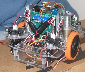
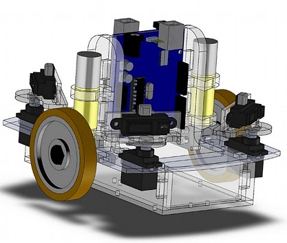
IRMa, the IR mapping robot, is a small robot, approximately 6" x 6" x 5", that I built for my Principles of Artificial Intelligence course. It was custom designed in Solidworks, CNC milled, and programmed on campus at Rutgers University. It has a sharp ir-ranger mounted on r/c servos at each of its four corners. The ir-rangers rotate and scan the environment around the robot. This allows IRMa to create a very cheap, noisy view of obstacles around the robot.
For my project, I wrote a program to have it autonomously map its environment. It can then save the map, be moved around the the environment, and find itself on the previously made map. For mapping, it uses a probabilistic model beam model of the IR ranger to compose the measurements on an occupancy grid. To localize itself on its prior map, it uses SURF features of the occupancy grid and a grid based Markov localization technique.
The robot itself uses 2 Arduino Decimillia boards for low level control. One board reads the sharp ir rangers and controls the servos while the other board does closed loop motor control for the two faulhaber gear motors that are mounted vertically in the center of the robot. Both of these Arduino's communicate wirelessly to a computer over a single Xbee. The computer is the brain. It receives the sensor data and directs the robot.
The computer program is built using ROS, the Robot Operating System by Willow Garage. It is composed of several different nodes that cooperatively manage the robot: a robot communication node, a map builder, a map localization node, a visualization interface, and a navigation node. Each of these nodes are separate programs that communicate to each other through ROS topics. These first three nodes I programmed myself while the latter two programs are configured components from ROS.
The communication node acts as the interface between the robot and the PC program. It manages the serial port connection to the robot, parses the communication, and publishes the sensor data to the other nodes. It publishes a Point cloud of the IR rangers and a odometry topic for the robot's position. It also subscribes to a geometry_msgs/Twist message on the cmd_vel topic.
The map builder node composes the noisy sensor data and constructs an occupancy grid map . It builds this map by probabilistically modeling each sensor reading as a beam with a gaussian at measurement point [1] and using a Bayes Update rule. It then publishes an occupancy grid map of the surroundings.
The localization program loads in a prebuilt map and compares the robots current map to the prior map. The analyzer first splits the prior map into a grid and creates a list of SURF features visible to the robot at each grid position. As the robot is moving around, it compares the current map to the prior map and computes the most likely grid location using Markov localization. As the robot moves around, the localization program zeros in on the robots location on the prior map. Typically this is within 30 seconds for its small (about 2.5 x.1.5 meters),simple environments.
For autonomous mapping, IRma uses a frontier based exploration agent based off of Yamauchi's "A Frontier-Based Approach for Autonomous Exploration." This node takes the map builder's occupancy grid and finds the frontiers, the edges between open space and unknown regions. It then selects the "best" frontier , i.e. the longest /closest frontier to the robot. The location of of the selected frontier is taken as the centroid of the frontier grid cells and this goal location is sent to the navigation node.
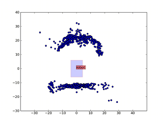

Left: Raw sensor data with a curved piece of cardboard in front of the robot and a straight wall behind the robot.
Right: Probabilistic model used to model the IR rangers. At the sensor measurement there is a high probability that the map is occupied.
Finally, by using ROS, the application gets two key components for free, visualization and basic navigation. For visualization, the program uses RVIZ to display a 3d model of the robot, the point cloud from the IR rangers, and the occupancy grid map. For navigation, the robot uses the ROS navigation stack. Once configured, the navigation stack takes goal position and orientations and sends velocity commands to robot. In its typical configuration, the navigation stack also creates its own occupancy grid based on the sensor measurements which it uses computing the robot's path. However, this was designed for high accuracy sensors like laser range scanners and does not work well for my noisy IR rangers. Instead, IRMa's navigation stack is configured to import its MapBuilder's map continually and generates a cost map from this map instead of the sensor measurements directly. With this combination in place, you can specify a goal location on the map and have the navigation stack guide the robot to that point.
The Solidworks CAD model for this robot is attached at the end of this article in both Solidworks format and as an eDrawing. Anyone is free to copy the design. The source code will be posted, I am in the midst of cleaning it up for public distribution. The robot to ROS interface has been uploaded and it is called pyRoboNode. It is attached below.
1. Matthies, Larry, and Alberto Elfes. "Integration of sonar and stereo range data using a grid-based representation." IEEE International Conference on Robotics and Automation 2 (1988): 727-33. Print.
2. Moravec, Hans P. "Sensor Fusion In Certainty Grids for Mobile Robots." Ai Magazine 9.2 (1988): 6174. Print.
3. Thrun, Sebastian. Probabilistic robotics. Cambridge, Mass: MIT, 2005. Print.
4. Yamauchi, Brian. "A Frontier-Based Approach for Autonomous Exploration." Proceedings of CIRA’97 (1997). IEEE Xplore. Web. 10 Dec. 2009.