
Abstract
Table of contents
- Introduction
- 1. Actuality of the theme
- 2. A review of research and development
- 3. Mathematical description of PMSM
- 4. Identification methods
- 4.1 Estimator using monitored stator voltages or currents
- 4.2 Model Reference Adaptive System (MRAS)
- Conslusion
- List of used sources
Introduction
Permanent magnet synchronous motor (PMSM) are used in a broad power range from mWs to hundreds kWs. There are also attempts to apply PMs to large motors rated at minimum1 MW. Thus, PM motors cover a wide variety of application fields, from stepping motors for wristwatches, through industrial drives for machine tools to large PM synchronous motors for ship propulsion [1]. The main application of pm electric motors includes industry [2]: public life, domestic life, information and office equipment [3], automobiles with combustion engines, transportation, defense forces, aerospace, medical and healthcare equipment, power tools, renewable energy systems, and research and exploration equipment.
Further, the essential operational principle of a permanent magnet in the rotor assembly, generating a steady magnetic field instead of the short‐circuit current found on asynchronous induction motor designs yielded many advantages for the machine designer, builder, and aftermarket. These advantages include compact form with high torque density and less weight, higher continuous torque over a wider range of speeds, lower rotor inertia, higher dynamic performance under load, higher operational efficiencies with no magnetizing current, and the corresponding absence of heat due to current in the rotor, low torque ripple effect, more robust performance compared to dc motors and good cos φ.
The challenges have been, of course, escalating costs of raw materials due to certain economic factors in the world market, though recent discoveries of rare earth magnets (REM) in the U.S. and elsewhere may affect that situation greatly in the future. In addition, the manufacturers are continuously addressing more technical aspects such as limited speed ranges in field applications and degradation due to counter voltage created by the magnets, where normally an encoder for commutation is deemed necessary, along with the inevitable limit overload condition.
1. Actuality of the theme
The main drawback of a PM‐Machine is the position sensor, which is vulnerable for electromagnetic noise in hostile environments and has a limited temperature range. Thus, the elimination of the electromechanical sensors reduces the hardware costs, reduces the installation complexity of the system (because of associated cabling), decreases the system inertia, increases the robustness and the reliability and reduces obviously the noise sensitivity of the electrical drive. In general, strategies for position estimation of PMSM can be divided to:
- Nonadaptive Methods:
- Estimators using monitored stator voltages or currents;
- Flux based position estimators;
- Position estimators based on back‐EMF.
- Adaptive Methods:
- Estimator based on Model Reference Adaptive System (MRAS);
- Observer‐based estimators.
- Saliency and Signal Injection: In many ac machines, the position dependence is a feature of the rotor. In the case of the interior PMSM there is a measurably spatial variation of inductances or resistances (saliencies) in the dq direction due to geometrical and saturation effects, which can be used for the estimation of rotor position. Another method to estimate the rotor position is to add a high frequency stator voltage (current) component and evaluate the effects of the machine anisotropy on the amplitude of the correspondent stator voltage (current) component.
- Artificial Intelligence: Artificial intelligence describe neural network, fuzzy logic based systems and fuzzy neural networks. These kind of methods do not require a mathematical model of the drive, exhibit good noise rejection properties, can easily be extended and modified, can be robust to parameter variations and are computationally less intensive [4].
Master's work is devoted to actual scientific problems sensorless vector control PMSM. The results will be verified by mathematical modeling package MATLAB\Simulink.
2. A review of research and development
Sensorless control of PMSM is a promising direction for research, as evidenced by the works of scientists around the world. Development on the subject began in the 80s of the twentieth century. Particular attention is paid to this subject in China (Jinsong K., Xiangyun Z., Ying W.), Japan (Morimoto S., Kawamoto K., Sanad M., Ichikawa S., Chen Z.), India (Benjak O., Mishara A., Mahajan V., Agarwal P.). Also research is being conducted in the United States and European countries (Schroder D., Schaffner C., Li Y.). Among domestic researchers engaged in the topic: Biletsky J.O., Spring G.I., Schur I.Z., Anischenko N.V.
3. Mathematical description of PMSM
Below is a mathematical description of the PMSM in the natural three-phase coordinate system. The latter can be transformed into the other, for example, by the Park transformation to a rotating flux oriented coordinate system d,q or biphasic fixed orthogonal system α‐β by the Clark transformation).

Voltages across the stator windings are defined by:
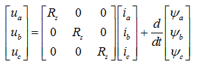
where:
ua, ub, uc – are the individual phase voltages across the stator windings,
Rs – is the equivalent resistance of each stator winding,
ia, ib, ic – are the currents flowing in the stator windings,
ψa, ψb, ψc – are the magnetic flux in each stator winding.
The total flux is defined by:
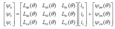
where:
ψm(θ) – are the total fluxes linking each stator winding,
Lxx(θ) – are the self-inductances of the stator windings,
Lxy(θ) – are the mutual inductances of the stator windings.
The inductances in the stator windings are functions of rotor angle, defined by:
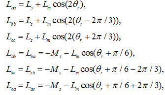
where:
Ls(θ) – is the stator self‐inductance per phase. This is the average self-inductance of each of the stator windings.
Lm(θ) – is the stator inductance fluctuation. This is the amplitude of the fluctuation in self-inductance and mutual inductance with changing rotor angle.
Ms(θ) – is the stator mutual inductance. This is the average mutual inductance between the stator windings.
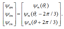
The linked motor flux is defined by:
Consider Lenz’s Law, electromagnetic torque is define by:
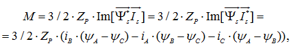
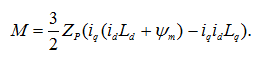
where Zp number of pole pairs.
Applying Park's transformation to the first two electrical defining equations produces the following equations in the rotor referenced, qframe :
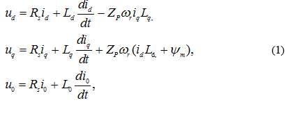
where:
ud, uq, u0 –are the d‐axis, q‐axis, and zero‐sequence voltages.
id, iq, i0 – are the d‐axis, q‐axis, and zero‐sequence currents.
Ld = Ls + Ms + 3/2 * Lm – is the stator d-axis inductance.
Lq = Ls + Ms - 3/2 * Lm – is the stator q-axis inductance.
L0 = Ls - 2Ms – иis the stator zero‐sequence inductance.
ωr – is the rotor mechanical rotational speed.
Torque equations in the rotor reference frame:
Using the Clark transformation α‐β frame can be obtained.
The simplest in terms of the requirements to a computing device and the ease of adjustment, are non-adaptive identification methods. However, they show the worst results compared with adaptive methods, which in turn are more difficult to configure and they require more computing time. The following are non‐adaptive method based on the stator currents and voltages and MRAS method.
4. Identification methods
4.1 Estimator using monitored stator voltages or currents
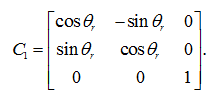
These technique uses equation of PMSM in rotor reference frame. General relationships can be established between quadrature and direct axes variables of direct stationary reference frame and the rotating reference frame by the following equation [5‐7]:

where superscripts r
and s
are used to denote rotating and stationary reference frame quantities, respectively. [C1] – is the coefficient matrix which is given by:
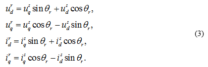
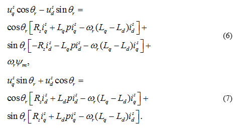
Substituting u and i for x in equation (2) and expanding the following equations are obtained
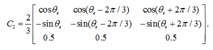
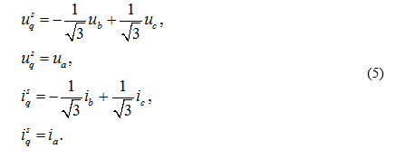
The relationships between three phase and orthogonal quantities in stationary reference frame are:
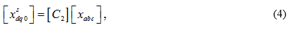
where:
Substituting v and i for x in equation (4) the following relationships are obtained:
From equations (3) and (4) the following relation can be obtained:
Transferring the orthogonal quantities of stator frame to three phase stator variables using equations (5‐7), the expression for the rotor position angle can be found as:
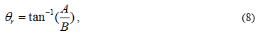
where:
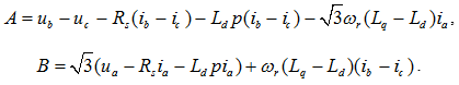
The position of rotor can thus be obtained in terms of machine voltages and currents in the stator frame provided ωr in equation (8) can be evaluated in terms of voltages and currents. For this purpose, equations (6) and (7) are used. Next, the d, q axis variables in equations (6) and (7) are replaced by three phase stator quantities using equations (5) and assuming Lq = Ld = Ls. The rotor speed can be evaluated as shown below: ωr:

where:
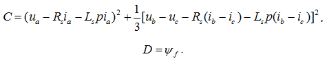
Fig. 4.1 shows plots of transient and shaft speed estimation error of PMSM.

Fig. 4.1 shows that the estimation error rate is less than 10 rad/s. Disadvantage is poor performance of the method at speeds close to zero, which is associated with low values of currents.
4.2 Model Reference Adaptive System (MRAS)
In this case, MRAS estimator uses two models to calculate a stator flux‐linkage of the PMSM. One model is a reference and the other is an adaptive model [8‐10]. MRAS block diagram is shown below.

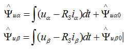
These two equations correspond to a stator voltage model, which does not contain the rotor angle and is therefore a reference model:
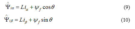
These two equations represent the current model, which contains the rotor angle, and therefore represents the adaptive model:
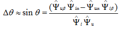
The outputs of these two models are compared in an adaptation mechanism to estimate the adjustable parameter that tunes the adaptive model in order to drive the output error between these models to zero.
The adaptation mechanism uses the angle error Δθ as corrective information to calculate the adjustable parameter θ in the adaptive model.
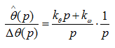
The adaptation mechanism, which estimates the adjustable parameter θ, is a PI‐type series controller with an integrator:
Simulations are carried out in the following modes: acceleration to full speed at idle, lashed rated load, braking to zero speed. For the simulation, the following motor parameters are used:

PI corrector coefficients were chosen experimentally. Transient and estimation error is shown on Fig. 4.3
 and the difference between the actual angle and the calculated (estimation error) (б)")
Conclusion
- The elimination of the electromechanical sensors reduces the hardware costs, reduces the installation complexity of the system (because of associated cabling), decreases the system inertia, increases the robustness and the reliability and reduces obviously the noise sensitivity of the electrical drive.
- The analysis of research and development on the subject showed the presence of a large number of methods for the angle identification. From the analysis, it follows that domestic publications do not provide expanded and structured description of the methods, as well as recommendations for their use. This leads to the need for more research in this area, which is devoted to this master's work.
- The simulation showed that non‐adaptive identification method based on voltages and currents is workable only at high speeds and under load. This is due to the large currents flowing in the stator windings, which are necessary for calculating the angle and speed. The speed estimation error is less than 10 rad/s. At low speeds, this method shows itself unworkable. Thus, it is possible to note the high sensitivity to changes in the parameters of the motor. Of the advantages of this method may be noted ease of implementation and the lack of need to customize.
- Simulation of MRAS showed that the developed system has characteristics similar to the characteristics of the system with an electromechanical rotor position sensor. Estimation error does not exceed 0.005 rad and increases with increasing torque on the shaft. Thus, MRAS solves the problem of estimating the angle of the rotor in operation of different modes of the motor. The simulation results showed that the developed system provides a speed range up to 1:50. The disadvantage is the lack of procedures for the selection corrector coefficients.
Since the writing of this essay, writing master's work is not yet complete, at this stage considered non-adaptive and part of the adaptive. In the future is planned to conduct a study and mathematical modeling of the most promising methods of identification, such as state observers, injection signals and artificial intelligence. Completion of the master's work: January 2015. Full text of the work and materials on the topic can be obtained from the author or his scientific director after that date.
List of used sourses
- Fracchia M., Sciutto G. Cycloconverter Drives for Ship Propulsion. Symp on Power Electronics, Electr Drives, Advanced Electr. Motors SPEEDAM’94, Taormina, Italy. – 1994. – pp. 255G260.
- Gieras J. F. Permanent Magnet Motor Technology / J. F. Gieras, M.Wing. – 2002. – New York. – p. 611.
- Jabbar M.A., Tan T.S., Binns K.J. Recent developments in disk drive spindle motors. Int Conf on Electr Machines ICEM’92, Vol. 2, Manchester, UK, 1992, pp. 381-385.
- Benjak O. Review of Position Estimation Methods for IPMSM Drives without a Position Sensor Part I: Nonadaptive Methods / O. Benjak, D. Gerling // XIX International Conference on Electrical Machines – 2010. – pр. 1-6.
- Hoque M.A. Speed and Position Sensorless Permanent Magnet Synchronous Motor Drives / M.A. Hoque, M.A. Rahaman // IEEE Anadien Conference on Electrical and Computer engineering, CCECE – 1994. – pp. 689-692.
- Jabbar M.A. Sensorless Permanent Magnet Synchronous Motor Drives / M.A. Jabbar, M.A. Hoque, M.A. Rahman // Canadian Conference on Electrical and Computer Engineering, CCECE – 1997. – pp. 878-883.
- Johnson J. P. Review of Sensorless methods for Brushless DC / J. P. Johnson, M. Ehsani and Y. Guzelgunler // IEEE Industry Applications Conference, IAS, Vol. 1 – 1999. – pp. 143 – 150.
- Vesely L. Sensorless Control for Synchronous Motors // L. Vesely, P. Zbranek // International Conference on Autonomous and Intelligent Systems (AIS) – 2010. – p. 1-5.
- Mishara A. MRAS Based Estimation of Speed in Sensorless PMSM Drive / A. Mishara, V. Mahajan, P. Agarwal // IEEE Fifth Power India Conference. – 2012 – p. 1- 5.
- Ichikawa S. Sensorless Control of an Interior Permanent Magnet Synchronous Motor on the Rotating Coordinate Using an Extended Electromotive Force / S. Ichikawa, C. Zhiqian, M. Tomita, S. Doki // Industrial Electronics Society, 2001. IECON '01. The 27th Annual Conference of the IEEE (Volume:3). – Denver. – 2001. – pp. 1667 – 1672.