
Ravikumar Setty .A, Shashank Wekhande A vant Garde Solutions Pvt Ltd, (Consultant to Allegro Micro Systems, USA) Mumbai,India.
Kishore Chatterjee Electrical Engg Department, lIT Bombay, Mumbai,India.
Abstract – Rotor position information is necessary to control PMSM (Permanent Magnet Synchronous Motors). Extracting rotor position information using physical position sensor presents several disadvantages, including increased size, reduced reliability, and additional cost of the whole system. To overcome these drawbacks, there has been considerable interest in sensor less control techniques. Sensor less control of PMSMs can be broadly classified as, fundamental model based methods and machine saliency based methods. Techniques that rely on the fundamental model have the advantages of simplicity and straightforwardness. However these techniques fail to extract rotor position information from low speed to standstill. In the last two decades, a number of high frequency signal injection techniques have been proposed and developed for PMSM rotor position estimation at standstill and low speed without position sensor. These techniques can be classified into continuous signal injection techniques, transient signal injection techniques and high frequency signal embed on to PWM. This paper gives an overview of various approaches to rotor position estimation from low speed to standstill using HFSI techniques. Finally comparison between different rotor position extraction schemes is presented based on hardware complexity, torque ripple, speed range and cost of current measurement system.
Keywords-Sensor less control; Model based methods; Signal injection methods; Initial Rotor Position Estimation; High Frequency Signal Injection; Demodulation Techniques; Continuous and Transient Signal Injection; INFORM and PWM excitation methods.
PMSM (Permanent Magnet Synchronous Motor) is electronically commutated and this control requires rotor position information. For PMSM, a constant supply of position information is necessary; thus a position sensor with high resolution, such as a shaft encoder or a resolver, is typically used. In most applications, the presence of such a position sensor presents several disadvantages, such as reduced reliability, additional cost and weight and increased complexity of the drive system. For these reasons, the development of position sensor less techniques is becoming an important research area.
Sensor less control uses only terminal variables (voltages and currents) to determine the rotor position. Application of sensor less techniques to PMSMs exists in the literature for more than two decades. Various methods of sensor less operation for PMSMs seen in the literature can be classified into two main categories, as shown in Fig. 1. Fundamental model based techniques are popular to control from medium to high speeds. These techniques works well above minimum speed [1], however all these techniques have serious problem to extract the rotor position from low speed to standstill [2].
At standstill, motor back EMF is zero, so all Fundamental methods fail to extract rotor position information. For Initial Rotor Position Estimation (lRPE), machine saliency is the key parameter. The idea behind saliency based sensor less estimation scheme is machine winding inductance is function of the rotor position due to saliency; so the rotor position can be deduced from the profile of inductance variation. Position estimation based on machine saliency or signal injection techniques are powerful from standstill to minimum speed. Extracting rotor position information based on machine saliency is practically feasible [4]-[9], [13]. Different High frequency signal injection schemes reported in the literature can be classified as
In continuous signal injection methods, a high frequency signal is continuously superimposed on the fundamental excitation. According to the type of injected signal, continuous signal injection consists of a rotating sinusoidal signal injection [3] [4], a pulsating sinusoidal [5] [6], a square wave signal injection [7], or arbitrary injection [8].
In transient signal injection scheme the saliency position information is obtained through current transient response when an impulse voltage vector is applied. The Indirect Flux Detection by On-line Reactance Measurement (INFORM) method [9] is a typical transient injection based technique. The major problem for the standard INFORM method is the introduced current disturbance due to addition of transient voltage vectors. To solve these problems, a compensation mechanism using double transient injection is proposed in [10]. The voltage vectors used in transient voltage vector injection methods also exist in standard PWM for normal operation. Therefore, it should be possible to measure the Current transient response introduced by the inherent PWM [11] [12] [13] [14].
Reference [16] uses zero-sequence excitation. There is no need to add a signal to the PWM or to modify it. This carrier has the same frequency as switching. Consequently, the position estimation has a fast dynamic response and no additional audible noise is produced. Because the excitation signal is in the zero sequence, it does not interact with the current controller. But in order to make the zero sequence voltage acting on the machine, a filter is employed.
Magnetic saliency methods are relatively complicated for real time implementation; however they work well for IRPE. Hybrid methods, which combine both fundamental and saliency based methods are also reported in literature [17]
This paper reviews various high frequency signal injection (HFSI) techniques applied in PMSM sensor less control. First, theoretical backgrounds related to the high frequency signal injection technique developed in both the synchronous and the stationary frame injection schemes. Finally a comparison of the main features and performance of the different High frequency signal injection techniques are discussed.
All signal injection techniques work based on machine saliency. This paper discusses the signal injection techniques for IPMSM (Interior Permanent Magnet Synchronous Motor). It is assumed that saliency causes a balanced sinusoidal three phase impedance modulation.
Fig. 2. shows the cross section of a machine indicating the three phase stator windings A,B,C. The shaded areas of the machine section symbolize areas with a high permeability (e.g. iron). The white area between the rotor and stator symbolize the relative air gap, where the permeability is assumed to be low. It can be seen that the relative air gap width changes with the position of the saliency dq' frame. Thevchange in the relative air gap changes the values of the resulting three phase equivalent inductances lA, lB and lC. The three phase equivalent inductances lA, lB and lC. are given by (1) to (3), which consist of a constant term L plus a sinusoidal modulating term ΔL depending on the saliency position angle(λdq`)

Transforming the three phase equivalent impedance vector into the αβ frame and dq' frame are given by (4) and (5).

For the analysis of the machine saliency only the current
response to the injected high frequency voltage is used. At the
high frequency range the voltage drop across the resistance is
much smaller than the voltage drop over the winding
reactance. As a result the simplified (6) is used to describe the
relation of the high frequency stator voltage and its high
frequency current response
and its high
frequency current response  . Equation (9) shows the
transformation into the stator fixed αβ frame. From (9) it is
clear that, current response for the injected high frequency
signal contains rotor position information. Based on this
principle different HF signal injection schemes reported in the
literature can be classified in to continuous signal injection
scheme and transient signal injection scheme.
. Equation (9) shows the
transformation into the stator fixed αβ frame. From (9) it is
clear that, current response for the injected high frequency
signal contains rotor position information. Based on this
principle different HF signal injection schemes reported in the
literature can be classified in to continuous signal injection
scheme and transient signal injection scheme.

This technique is based on injection of a high frequency signal on top of the fundamental signal. The technique can be divided into several different methods with different approaches to obtain the rotor position. The injected high frequency signal can be rotating or pulsating, injected in stationary,αβ, or rotating in dq-reference frame.

A constant amplitude voltage vector rotating at high
frequency (500 to 2500 Hz) is superimposed on the
fundamental voltage vector. The injected high frequency
voltage vector  is defmed by (10). Therefore a rotating
HF current vector arises superimposed to the fundamental
current vector. The high frequency current response is filtered
out by a band pass filter from the measured machine currents
and then demodulated to reconstruct the rotor position.
Current signal contains rotor position information, but all the
current signals at the injection frequency are hidden in the
much stronger fundamental stator current and the switching
harmonics. Heterodyning demodulation and homodyning
demodulation methods are used to extract the rotor position
signals from the measured stator currents.
is defmed by (10). Therefore a rotating
HF current vector arises superimposed to the fundamental
current vector. The high frequency current response is filtered
out by a band pass filter from the measured machine currents
and then demodulated to reconstruct the rotor position.
Current signal contains rotor position information, but all the
current signals at the injection frequency are hidden in the
much stronger fundamental stator current and the switching
harmonics. Heterodyning demodulation and homodyning
demodulation methods are used to extract the rotor position
signals from the measured stator currents.
Heterodyning detection is a method which consists of detecting a modulated signal by multiplying it with an intermediate signal between the carrier signal and the signal to be transmitted. Several researchers have used heterodyning demodulation scheme to extract the rotor position [18]. Homodyning detection technique is an improvement of the heterodyning demodulation. The homodyning demodulation scheme is also used in the literature to extract the rotor position [19].

The same C measured phase currents are used as feedback for the fundamental current controllers after the injected HF currents are filtered off by a low or band stop filter. Fig.3. shows the block diagram of the rotating HF voltage injection principle. Limited dynamic bandwidth of system due to signal demodulation process is the major drawback. To solve this problem, square wave signal is injected in the estimated d-axis which eliminates the requirement of low pass filters for signal demodulation, hence sensor less dynamic performance is claimed to be remarkably enhanced with this method. In [7], an effective solution with integration of pulsating square wave injection and current control loop is proposed for sensor less control of low salient surface mounted PM BLAC machines.
The HF voltage is added to either the estimated die or q'e axis. Therefore in sensor less operation the injection of the HF voltage directly depends on the estimated dq'e reference frame position.The injection of the pulsating HF voltage is usually made on the die axis. Therefore the resulting HF current ripple affects mostly the flux producing fundamental current in d axis. In PMSM's the variation of the d axis current has only a little effect on the rotor flux due to the relative larger air gap. Thus the effect on the resulting machine torque is minimal. In PMSM's the fundamental current of the d axis is mostly set to zero.
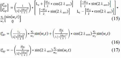
Equation (14) shows the definition of the injected pulsating high frequency voltage vector for the case that the injection is done in d'e direction.

Equations (16) to (17) show the expression for the resulting current response to the injected pulsating HF voltage into d'e direction. The resulting HF current component in the estimated quadrature axis q'e (for injection in d'e axis) is used for position tracking. It can be seen from (17), that this term decays to zero for the case in which λerr = O. Therefore, the sensor less algorithm adjusts continuously the direction of the pulsating voltage injection until this condition is met.
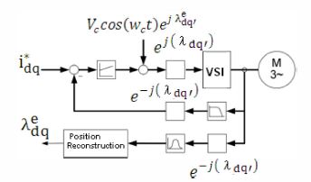
FigA. shows the resulting block diagram of HF voltage carrier injection in d axis. The demodulation is done with a heterodyning scheme. A low pass filter can be implemented for the carrier frequency removal in the demodulated signal.
However, some implementations do not use a low pass filter, but feed the HF signal directly into the PLL controller input. This minimizes phase lagging for the position estimation that might be introduced by the low pass filter. The high frequency component is then inherently filtered out by the limited band width of the PI controller. As an alternative [6] uses a bang-bang controller. In this case a low pass filter to filter out high frequency of the demodulated signal is necessary due to high bandwidth of the bang-bang controller. Injection of the pulsating HF voltage into the machine q'e axis can reduce inverter disturbances.

However, the trade off are larger torque ripple caused by HF current ripple. Table I compares pulsating injection and rotating injection methods.
Position estimation accuracy in high frequency signal injection techniques affected by non-linearity of the power inverter. The high frequency currents can be distorted by the dead-time and the device voltage drop. Some inverter nonlinearities can produce a fictitious saliency, whose origin is not in the machine. A different approach to detect the saliency modulation of the machine inductance is to introduce impulse transient conditions on the machine stator windings. In this case dedicated active voltage vectors are applied at certain points of time.
The Indirect Flux Detection by On-line Reactance Measurement (INFORM) method [9] [10] is a typical transient injection based technique. Additional impulse voltage vectors are superimposed during zero vector dwelling for standard PWM. Meanwhile, the current derivative measured is synchronized to the test voltage vectors. A pair of test vectors in opposite directions on the voltage phase plane is applied, within a null vector of one PWM period, such that their total effect on the output voltage is zero.

Assuming the stator current and back EMF(Electro Motive Force) values are unchanged during these two adjacent test vectors, the influence from back EMF and resistive voltage drop can be easily cancelled. The last three measurement pairs of the three phase directions are continuously combined to P shown by (19) whose argument gives the position information.
Due to a minimum duration being required for the transient impulse vectors, it is difficult to obtain all di/dt sampling for position vector construction in one PWM cycle. Hence, three sets of test signals, each of which consisting of a pair of opposite voltage vectors, are applied on successive three PWM cycles. As a result, the position estimation would take three PWM cycles. The major problem for the standard INFORM method is the introduced current disturbance due to additional transient voltage vectors. Furthermore, the rotor position is assumed to be constant during the successive three PWM cycles, which is reasonable for standstill and low speed operation. However, the position change could not be neglected at higher speed. To solve these problems, a compensation mechanism using double transient injection is proposed in [10]. Table II compares the INFORM and Modified INFORM methods.
The voltage vectors used in transient voltage vector injection methods also exist in standard PWM for nonnal operation. Therefore, it should be possible to measure the current transient response introduced by the inherent PWM, so as to extract the saliency position infonnation. The major advantage of PWM excitation is no requirement of additional transient voltage vector injection, which is used in the transient injection approach, which introduces some problems, including additional current ripple, higher switching loss, and limited dwelling time of zero voltage vector. The zero vector current derivative (ZVCD) method may be the simplest candidate among PWM excitation based techniques [II], which does not make any change on the standard PWM. Different combinations of measured current derivative in response to specific voltage vectors can be used to construct the position vector from which, the saliency position information can be obtained [12] [13] [14] .
In [15], an extended modulation (EM) scheme is presented to obtain saliency position using the current transient response introduced by modifying the PWM excitation without any additional injection.
For standard PWM excitation, the minimum duration of voltage vector could not be guaranteed at all time, since the duty cycle of the PWM is dependent on the fundamental voltage reference. To solve this problem, i.e., guarantee enough duration for specific voltage vectors, some techniques such as edge-shifting [13] [14] and extended modulation [15] are presented. In [20], it is found that the 2nd PWM harmonic has the largest amplitude, which can be considered as a pulsating vector, rotating approximately synchronously with the fundamental voltage vector. Therefore, the resultant 2nd PWM harmonic current together with the inherent 2nd PWM harmonic voltage can be used to extract rotor position information. The zero sequence excitation introduced by standard PWM is also proven to be effective for saliency based position estimation [16]. Table III compares PWM excitation based sensor less control techniques.
This paper compared continuous, transient high frequency signal injection (HFSI) techniques and PWM excitation methods without additional signal injection. Table IV shows the comparison of various high frequency signal injection techniques. The common idea of each technique is to apply some test voltage signal to the machine that excites the winding inductances. The current response is then used to retrieve the information about the saliency position. These saliency based methods are parameter insensitive and also work at zero mechanical speed.
In continuous high frequency voltage injection, the resultant current signal useful for position estimation is buried in the large stator current and other high frequency components. SNR ( Signal to Noise Ratio) is proportional to the amplitude of injected voltage signal. Larger SNR results in easier demodulation and better estimation results. But the increased injection signal amplifies the torque ripple, power losses and the acoustic noise. In transient techniques the fundamental current is not disturbed by a fixed high frequency component, but results in significant spikes during the test vector instances.


The main problem is the required minimum acquisition time for the measurement. The artificial extension of the active measurement voltage vectors causes significant current deviations. The major advantage of PWM excitation is no requirement of additional transient voltage vector injection, which is used in the transient injection approach.