
D. Yousfi, Member, IEEE, A. Halelfadl and M. EI Kard Ecole Nationale des Sciences Appliquees - Marrakech MESESYP Laboratory, Control Systems, Power Electronics and Electric Dives Group Avenu Abdelkrim Elkhattabi, B.P. 575 Gueliz, Marrakech Morocco Tel: +212 52443 4745 /46, Fax: +212 52443 4740. Email: dryousfi@yahoo.com
Abstract – The paper describes the comparison between four different high-performance techniques used for the sensorless estimation of the motor shaft position in Permanent Magnet Synchronous Motor Sensorless Drives. Rotor position and speed are estimated from either electrical measurement or Hal effect pulses, and are used as feedback in a sensorless vector control scheme, achieving almost the same highperformance of a sensored drive. The paper point out the differences, by using experimental implementation, between the four methods: Open-loop flux estimator, Flux algebraic Estimator, Reduced flux observer and Hall effect pulses based estimator.
Keywords – PMSM vector control, sensorless, flux estimator, reduced observer, Hall effect sensor, comparative study.
Vector controlled Permanent Magnet Synchronous Motor (PMSM) need an encoder or a resolver to correctly align the stator current vector. Such an electromechanical position transducer is not present in the other drives, thus disadvantaging PMSM drives in medium and low power applications.
To overcome this weakness, several sensorless strategies for PMSM vector control, based on different position and speed estimation techniques have been proposed in last years [1]. Generally, they consist of processing stator voltage and current measurements or Hall Effect pulses to perform the sensorless estimation of the mechanical quantities
Among the proposals in this field, some approaches seem to be most interesting since they do not need any additional hardware i.e. the electrical model based techniques [8] and the state observer based techniques [2-4], or they require a low cost Hall effect sensor only [11].
From the mentioned families, the paper consider precisely:
- An open-loop electrical model based flux estimator.
- A flux algebraic estimation based technique.
These methods were developed in our laboratory [7,11].
- A reduced flux observer which is derived from an
existing full order Luenberger observer [5,6], and
improved to achieve good performance.
- A Hall Effect pulses based estimation technique which
is under investigation.
In this section, a brief description of the PMSM models are described since three of the investigated estimation methods need to manipulate the equations of the machine. The models of the PMSM in the stationary frame (α-β) and the rotating frame (d-q) are respectively:
where Φm is the maximum phase flux linkage of the permanent magnet, Lαβ and Ldq the inductances in αβ and dq frames, R the winding resistance and θ the actual rotor angle.
As the considered PMSM is a non-salient machine, all the inductances are equal .i.e. Lα=Lβ=Ld=Lq=L.
On the one hand, the rotor angle is of critical importance for successful control of the synchronous motor. On the other hand, speed feedback is required to accurately track the velocity reference in a speed control loop. That's why, in absence of mechanical sensors, suitable strategies must be developed to determine these parameters (Fig. I).
Position sensing via flux-linkage variation has been known for many years , but its successful implementation has become possible only in the last decade with the emergence of devices with sufficient real-time processing power.
The first investigated technique belongs to this category of estimators. It is based on an open-loop flux linkage estimation and PI-controller. Accurate flux linkages are derived from the back-emf by means ofa modified integrator.
The estimation algorithm involves the following steps [7]:
Step 1:
Estimation of the flux linkage in a,B-frame by measuring the phase voltages and currents:

Step 2:
Estimation of the motor currents

Step 3:
Calculation of the difference between the actual currents and the estimated ones in α-β and d-q frames:

Step 4:
Finally, a PI-Controller is used to cancel the obtained error
by accelerating or decelerating the  frame.
Thus, the PI- Controller output is the estimated speed
The position estimate can be deduced through an
integration and corrected using Look Up Table procedure that
gives a correction term Δθ so:
can be deduced through an
integration and corrected using Look Up Table procedure that
gives a correction term Δθ so:

The flux is used, in the first method, to estimate the rotor angular position. In steady-state, especially, the actual flux linkage vector is synchronized to the rotor and the flux linkage vector position is the true rotor position. However, because of the measurement imperfection which must be corrected by means of filter, an error occurs in the phase angle and magnitude of the flux linkage estimation. This uncertainty depends on the speed, and it increases when the motor operates at a frequency lower than the filter cutoff frequency .
The integration of(5) by pure integrator (l /s) involves drift and saturation problems. Since the integration at t=Os time instant requires initial condition, the rotor must be brought to a known position. However, this prior setting is not always possible.
To avoid the pure integrator and solve the problems, the authors propose in [11] a method that make use of the fact that the flux ψα and ψβare respectively cosine and sine function of the position. They can be derived, immediately, from the backemfs eα. and eβ by using the following algebraic calculation:
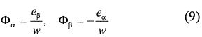
In this way, there is no need of the position or the flux linkage initial values.
In practice the back-emf measurement, used to evaluate the flux estimate, contains an offset which causes additional position error. This problem is removed previous to any processing (Fig. 2).
As formulated in this section, the stator currents and voltages as well as speed-based division, are used to construct a rotor flux estimator. In addition, LP filters are inserted in the estimation line. Such arrangements induce, of course, additional position errors.
So, based on the above considerations, a Look Up Table procedure is implemented to compensate the position estimation error.

State observers require the use of a relatively accurate motor model, the measurement of the motor currents (system output) and the knowledge of the feeding voltages (system input).
The basic idea is to use the difference between the state variables and the estimated state variables to calculate the rotor position and speed, directly or through related variables. Several sort of approaches are reported in literature [2-4]. They exhibit different peculiarities in term of algorithm complexity and sensitivity to parameter variation and noise.
The used observer is based on the flux linkage model of the PMSM in a two phase stationary fram e as shown in the following equation:

The input vector and the full state vector are respectively:
The aimed state s are:Φmα=Φmcosθe and Φmβ=Φmsinθe
And the output vector is the measured currents:
In the state space model ωe and θe are the electrical rotor speed and position and γ = R / L.
To consider the reduced version of the above observer a reduced vector and matrix are introduced as follow:

 is the estimate state and Gr is the reduced observer gain.
The model can be considered as a linear time varying system. And with appropriate calculation of the matrixes Gr Bo and Ko the state error continually vanishes. The rotor position estimation is calculated by the arctg operation:

Fig. 3 shows the resulting observer scheme.

It is clear from (10) , (12) and (13) that rotor speed is required first for the implementation of the flux estimation in the methods Band C. A simple manner to estimate its magnitude is given by [6]:

where, δ an adjustment coefficient.
The pos sibility of starting up the motor from standstill with thi s technique is the main reason that incites to investigate it.
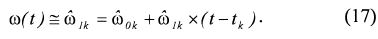
High-resolution rotor position estimation is obtained through digital processing of the Hall Effect sensors outputs. These sensor s detect when the rotor magnetic axis enters a new 60° sector. The electric angular pos ition is given by:

where ω(t) is the instantaneous electric angular velocity, tk is the instant in which the magnetic axis enters sector k (k= I , 2,... , 6) and θk is the initial angle of sector k, measured from a fixed reference axi s.
A position estimation algorithm based on the Taylor series expansion has been studied.
The zeroth-order position estimation algorithm, introduced in [12,13], is obtained by taking into account only the zerothorder term of an approximated Taylor series expansion. This algorithm con siders the speed inside each sector to be constant and equal to the average velocity in the previous sector.
Rotor speed can then be expressed as zeroth-order Algorithm:

where Δk-1 is the time interval taken by the rotor magnetic axis to cross the previous sector k-l.
Or First-Order Algorithm by taking into account higher order terms of the Taylor series expansion [16]:
In (20), the first derivative is approximated as

Obviously, special attention should be paid to the sampling time choice.
The electric angular position can be obtained by numerical integration of (15), applying the constraint that the resulting angular position value has to be within sector k limits. The angular position is, thus, calculated as

Although it is possible to use higher order approximations, only the first-order one has been considered because of increasing computational times.
Simulation results concerning the Hall Effect pulses based technique, that is not implemented yet, are presented in Fig. 4. The figure shows a starting up of the motor followed by a step transition between 500 and 1000 rpm at 100 us sampling time. Except in the staring up moment, when the position error reaches 50, this error is always in ±1.10 interval; and the speed estimation is excellent.

More investigation is required for the low speed behavior before the experimental implementation of this estimator.
To carry out an experimental verification of the three techniques A, Band C, a laboratory setup consisting of 500W three-pole PMSM fed by an IOBT Voltage Source Inverter, is used. For estimation and control tasks , a dSpace OSII 04 board has been used. In order to compare the estimated position and speed signals with the actual output, an incremental encoder is also mounted on the drive shaft.
The sensorless PMSM drives are demonstrated to operate in satisfactory manner, even at very low speed, with the studied techniques:
A. Open-loop flux estimator based technique .
B. Flux Algebraic Estimation Based Technique .
C. Reduced flux observer based technique .
The figures show the speed estimates (in rpm) and the position errors (in deg): in low speed operation and in varying speed and considerable load conditions.
The positional error, in all conditions, is measured to be within: ±1.50 for the technique A, ±70 for the technique Band 10 for the technique C.
The rotor speed errors are less than /% along the investigated speed range (up to /200rpm) for all the techniques. The quality of the drive is not affected significantly anyway.
When the mechanical sensor is replaced by an estimation technique that provides the rotor position and speed, all the control methods commonly used in sensored control of the motor are conserved in the sensorless scheme. That is the major advantage shared by the presented sensorless techniques.
On the other hand, the major difference between these techniques results from the flux estimation which is carried out by an open-loop calculation in the method A and S, and by a closed-loop one in the C method. So, the flux observer based technique is a self-adjusting flux estimation method.
In the following section the effects of different factors on the rotor position and speed estimation accuracy are investigated.
Starting difficulty is a challenging problem in sensorless operation of PMSM drives. For a simple starting, the test motor is started up in open-loop operation as a stepper motor with sinus-wave excitation until the rotor speed reaches convenient level for angle estimation.
The lowest sensorless speeds are 25 rpm for the technique A, 30 rpm for the technique Band 33 rpm for the technique C.
As described in section III the rotor speed, in the open-loop flux estimation based technique, is obtained by closed-loop estimation using PI-Controller. That is the reason of the good estimation results of this quantity.
However, in the method Band C, the speed is estimated separately and it is considered to be a system parameter in the flux observer (10,11). Therefore the position estimation accuracy is dependent on the accuracy of the speed estimate, which depends itself on the PM flux linkage Φm (14).
Not including an adaptive correction scheme, PM flux linkage uncertainty would generate velocity estimation error, particularly in low speed rang. As, in such condition the backemf signals derived from the measured current and voltage are feeble. Additional procedure is then necessary to remove the effects of this uncertainty.
The first indirect position sensing method requires the measurement of the stator current and voltage waveforms. The use of these measurements in the rotor position estimator will result in angle estimation inaccuracy owing to the inevitable scaling or offset errors contained in the sensed quantities.
In practice, the open-loop integration (5) is prone to errors caused by drift. Small offset signals in the measurements are summed over time, causing the integrator output to saturate. Furthermore, an initial value problem associated with the pure integrator occurs from the integral value at the initial instant.
Integrator drift can be reduced by improving the pure integrator with a low-pass filter with very low cutoff frequency. Another way to solve this problem consists in replacing the integrator by an alternative integrator structure [7]. But these modifications have two drawbacks: the inhibition of the flux estimator in low-speed range and the phase lags induced by the filter. Consequently an additional position error arises.
Based on the above considerations, a Look Up Table procedure is implemented to compensate the position estimation error. The estimation algorithm becomes then more complicated.
In the reduced flux observer based technique, selecting the magnitude of the closed-loop eigenvalue reals to be much greater than the angular velocity helps to reduce the effect of voltage measurement offsets on the rotor position estimation accuracy.
When the presented estimation methods are compared in their complete version, the reduced flux observer based technique seems more complex in term of formulation and practical implementation. But in actual fact, the closed-loop flux estimation achieved by this technique makes it more attractive; especially if the problem of the speed estimation in low speed rang is resolved by using a position derivation instead of the back-emf based calculation. Furthermore, with appropriate parameters adjusting the observer based technique presents a good immunity against motor parameters uncertainty and electrical measurement defaults.
Basically, the main limitations of the investigated solutions refer to standstill operation and safe starting due to the unobservability of rotor angle under those operating conditions. This problem can be surmounted by using the Hall Effect pulses based technique that allows a starting up of the machine as a Brushless DC motor. Next, the pulses are used to achieve a very accurate estimation of the rotor position and speed.
In many industry applications, initial positioning is not necessary and a simple open-loop starting up can be used. In the opposite case, starting method should be involved in the whole sensorless algorithm.