
Abstract
Substantiation of the basic parameters of the optimal airlift-dredge systems for the treatment of slage in land reservoirs
Content
- Introduction
- 1. Theme urgency
- 2. The purpose and objects of the study
- 3. Airlift. General, the basic theory
- 3.1 The principle of operation
- 3.2 Features airlifts
- 3.3 Classification features
- 3.4 Description of hydraulic circuits
- 3.5 Principles of similarity theory and modeling
- 4. Beaded (slug) airlift operation
- 5. Movement of solids in a vertical pipe
- 6. Movement of solids in horizontal pipelines
- 7. Airlift-dredge complexes
- Conclusion
- References
Introduction
One of the most promising areas of technological progress in transportation is the development of hydraulic transport. Thanks to the well-known advantages of this type of transport is used when moving minerals (sand, gravel, petroleum and petroleum products, salt solutions, and more) from the place of production to the consumer, waste rock stockpiles to; waste preparation plants; ash and slag dumps at thermal power stations, and more
Hydro mechanized is the main way to teach loose production of building materials (sand, pebbles, gravel, etc.), using dredges equipped groundwater pumps. Limiting factors in hydro mechanized booties loose building materials from the bottom of ponds and use of traditional dredgers with groundwater pumps is a low concentration of hydro mixture (10%) and very deep excavation (up to 10 m).
Therefore, the most rational use of airlift facilities.
This was confirmed by theoretical and practical study of the Donetsk Polytechnic Institute (since 1993 Donetsk State Technical University) (Ukraine) and other research centers as well as operating experience they created hydro systems. Airlift-dredge complex (ADC) for production of building materials, developed by scientists DPU, unlike s from dredgers have a greater range to feed the pulp with a high concentration (70%) of solid material and the depth of excavation (from tens to hundred meters). Tested these airlift shells on the Sea of Azov, Baltic and Black Seas, in the waters of Western Siberia in the extraction of sand and gravel, prey piloidiv (Berdyansk resort area), prey sapropel (Belarus) and others.
Airlift (air lift) is a hydraulic device for lifting or just a drop of liquid, or a drop of liquid and solid material by using pre-compressed in the supercharger and mixed with a drop of this liquid air. As your agent can be used not only air, but also gas or vapor.
Compared airlift are widely used in various industries due to significant advantages over other types of hydraulic head:
- simple design;
- no moving or rotating parts;
- high reliability and durability;
- simplicity and ease of operation;
- self-tuning, which can operate in automatic mode;
- high concentration and amount of solid material in lifting the pipe;
- significant opportunity to dive airlift suction device (hundreds of meters), making it in this application apart from the competition as well as the normal-depth groundwater pump;
- little operationally technological process
- smooth and easy feed control (performance);
- continuous process;
- relatively small flow area of wear;
- relatively low costs of installation, maintenance and repair;
- environmentally harmless, reduces environmental impact reduction plane design.
The main disadvantages of airlift are:
- smaller compared to other fluid (pumps, coal pumps) efficiency;
- low pressure;
- decrease with a decrease in feed and depth of immersion of the lift pipe deflection from the vertical position.
Use of ADC, in some cases significantly increases the economic efficiency of hydraulic. Given the conditions under which the work ADC may achieve increased productivity in the 2 - 2.5 times compared to modern industrial suction-equipped groundwater pump.
Thus, based on the above advantages, airlift-dredge complexes (ADC) for treatment of sludge bottom of inland waters in Donetsk, we can conclude about the feasibility of using ADC to clean the sludge from the bottom of the urban ponds Donetsk Kalmius River.
1. Theme urgency
Theme of master's work all the more urgent, planned to clean the city of lakes Donetsk using dredger. A master's thesis conducted in the calculation of the ADC with the aim of finding optimal parameters of the complex in the specific conditions of the first city of Donetsk rate can be used by the contracting organization to a more rational use of energy, material and human resources.
2. The purpose and objects of the study
Purpose - to improve the efficiency of hydro treating sludge First City of Donetsk rate through the use of ADC.
Objectives of the study
- consider the basic theory airlifts;
- make experimental investigations of motion solids in water-flow;
- make experimental studies weighing particulate fluid flow in horizontal pipelines;
- perform hydraulic calculation and selection of the compressor, groundwater pump;
- calculate the power supply ADC;
- perform technical - economic calculation ADC.
Object of study - workflow airlift in airlift-dredge complex for hydro treatment of silt inland waters.
Purpose of the study - the parameters of the workflow airlift.
Research methods - analytical calculations, analysis of theoretical and experimental studies of EMS department and compilation of data from the literature to substantiate the problem, formulate research problems.
3. Airlift. General, the basic theory
Plenty of structural and scheme decisions of airlift, conditioned by their application in different industries of production, the general elements of vehicle, realizing the process of getting up of liquid, it is been (fig. 3.1) : lifting pipe 1, tube 2, air tube 3, air separator 4, source of the compressed air 5.
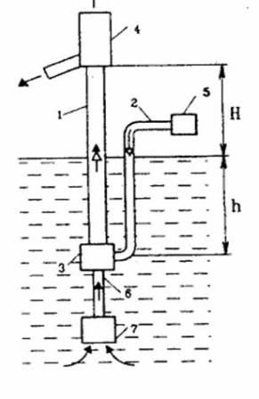
Figure 3.1 - Schematic diagram of the airlift
Figure. 3.2(animation) - Starting modes and operation of airlift (positions: 1 - air supply pipe 2 - Mixer 3 - the feed pipe, 4 - lift pipe 5 - air separator) (the number of frames - 21, the number of repetitions is unlimited size 109KB, created in Easy GIF Animator 2.0)
In the airlift designed for lifting slurry of solid material, the lower part of the lift pipe connected to the mixer, is joined via underwater pipeline with 6 suction device 7. For normal operation of airlift needed some geometric immersion h mixer (distance from the water level in the reservoir to the point of entry of the compressed air in the mixer), the size of which depends on the height H (distance from the water level in the reservoir to the discharge point of the pulp with air separator) slurry and ranges from a few meters to hundreds of meters. Thus from an economic point of view relative dive ![]() should be more 0.15.
should be more 0.15.
3.1 The principle of operation
The principle of operation airlifts are dynamic friction pumps. They slurry rises under the action of forces generated by the relative movement of the air and the slurry. Transferring the mixture of air and pulp - aero slurry - occurs due to the difference flow rate of air introduced into the airlift and the mixture leaving there from.
Fig. 3.3 - Phases start airlift
In Fig. 3.3 the four main phases starting airlift. Phase a - supply airlift zero static pressure is determined by immersion mixer h.
(3.1)
where ![]() - density of the fluid around the jacking pipe.
- density of the fluid around the jacking pipe.
When feeding air into the air supply pipe 1 begins the process of displacement of fluid from the latter through the mixer 2 to 4 lift tube and then through the lower part and well (supply pipe 3) into the reservoir, which determines a gradual increase in pressure of the compressed air, the maximum value is achieved at the moment approach re d it to the front air mixer (phase б)
(3.2)
where hп excess air column in lifting the pipe during start-up, the value of which depends on the displacement fluid resistance path from the mixer to the output of the reservoir and the velocity of the fluid displaced.
After the complete displacement of fluid from the air supply pipe, air enters the mixer, where the mixing process of air (gas), formed from a liquid slurry starts to fill the lift tube. When continuously injecting air into the mixer lift pipe is filled with a mixture of air and liquid density ρсм which is less than the density of the liquid, therefore the level of the mixture in the riser is established above the liquid level outside the pipe. Further progress of the movement of the slurry in the riser depends on the flow of compressed air. In practice, the operation of the notion of zero-mode
, which refers to the normal and pray case when the specified gas flow rate (air Qво), level air and melon mixture in lifting the tube at the level of discharge, but there is no ejection of the liquid (Figure 3.3). Pressure in the mixer Рсмin this case will be approximately equal to the pressure of the liquid column at the mixer.
Further increase in the air flow leading to the drain water mixture from the riser pipe (Fig.3.3 d) air separator 5, where the section, attitude air and fluid (Qв.р. and Qe.p ). The pressure in the mixer Рcм.р thus be lower than the pressure of the liquid column pressure loss in the amount of movement in the supply pipe 3 airlift.
3.2 Features airlifts
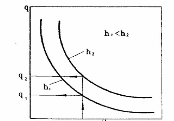
Figure 3. 4 - Activity and flax dependence q =f(α)
The main parameters of the airlift, besides the above h and H are: feed Qe, area of several m3/h, up to several thousand m3/h, of compressed air flow QВ, specific air flow ![]() and lifting pipe diameter D. Between the size of q and α there is a functional dependence q = f (α), (Fig. 3.4) experiment is obtained from Donetsk Polytechnic Institute (DPI) and experimentally used to calculate the airlift.
and lifting pipe diameter D. Between the size of q and α there is a functional dependence q = f (α), (Fig. 3.4) experiment is obtained from Donetsk Polytechnic Institute (DPI) and experimentally used to calculate the airlift.
Figure. 3. 5 - The output (1) and energy (2) characteristics of airlift
The dependence of Qэ =f1(Qв) ) is a costly feature is airlift (Figure 3.5). This characteristic has some specific points. Begin feeding slurry, when a certain air flow Qв.о is optimal point К, located at the site of the collision tangent drawn from the origin and corresponds to the maximum efficiency on energy η=f2(Qв) characterization of airlift. Point M corresponds to the max i mal feed (hump
), followed by a decrease with increasing feed airlift in and waste of air. Business Area AB, corresponding optimum efficiency, ηопт=0,85ηmax , where airlift operation economically feasible.
Numerous studies conducted are Logvinov N.G. (DPI), was found a great property that allowed the build properties is costly airlift [1]. This finding is as follows This discovery is as follows. If all the characteristics present in the dimensionless form, taking as a reference value of compressed air consumption and supply airlift to optimal conditions, the thus obtained dimensionless regime points lie on a single curve. Selecting analytical function construction was based on the analysis of experimental data, and from which it follows that the best for presenting research data, expressed in dimensionless form, is an appropriate choice of the scale of the dimensionless coordinate equations arc:
(3.3)
In the construction of costly specifications for the dimensionless cost c and syllable Air
(3.4)
and dimensionless innings airlift:
(3.5)
must choose the same linear scale, namely ![]() and swirl and then reap all the experimental data over these normalized scale. In this regime the dimensionless points lie on a single curve, which is the arc of a circle of radius
and swirl and then reap all the experimental data over these normalized scale. In this regime the dimensionless points lie on a single curve, which is the arc of a circle of radius ![]() with center, which has coordinates
with center, which has coordinates ![]() and
and ![]()
In Fig. 3.6 presented dimensionless flow characteristic airlift.
Figure. 3. 6. Dimensional and dimensionless characteristics of airlift
Знаючи розрахунковий оптимальний режим для даного ерліфта, що має параметри оптимальних подач ![]() and compressed air consumption
and compressed air consumption ![]() - multiplying by normalizing coordinates dimensionless flow characteristics to the corresponding optimal values of consumption and supply airlift:
- multiplying by normalizing coordinates dimensionless flow characteristics to the corresponding optimal values of consumption and supply airlift:
(3.6)
and
(3.7)
obtain cost-dimensional characterization (Figure 3. 6).
Point P characterizes the operating mode of the air lift with the main parameters ![]() and
and ![]() at the end an amount of activated compressors.
at the end an amount of activated compressors.
3.3 Classification features
Variety of areas of use of airlifts, a wide range of technical parameters and design solutions identified the need to choose classification criteria, which could give a specific characteristic of the projected airlift.
Accumulated experience in preparing technical specifications for the establishment of air-lift units and their design has identified the following classification criteria:
- hydraulic;
- type supercharger compressed air;
- constructive;
- circuit;
- type of environment that is transported;
- production appointment.
Depending on the method of introducing a gas (air) in the riser pipe are divided into airlifts compressor and vacuum. In the compressor airlift gas (air) is compressed to a certain extent and the blower duct through the mixer is fed into the riser. In the vacuum airlift using vacuum pump connected to the air separator at the top in the riser, and a vacuum duct air is sucked in by the mixer. Known airlifts and combined vacuum - introducing air compressor. Vacuum airlifts should be used when it is impossible to create a receptacle with an effective immersion mixer [2].
In the constructive relation classification based on airlifts constructive solution mutual arrangement lifting and air supply pipes. Typical schemes airlifts on this basis are shown in Fig. 3.7.
Fig. 3.7 - Airlifts scheme depending on the relative position and the lifting air supply pipes: а) - with ring lift tube and the internal gas summing, б) - with separate gas summing, в) - with a ring of gas and summarizing an internal arrangement of the riser pipe.
Primary, the most universal, the scheme (Fig. 3.7 б) with separate duct (system SE-Field) located parallel to the lift line. In this system, the influence of (abrasive, corrosive, etc.) transported medium to the duct, but the installation process is complicated.
Scheme with ring lift tube and the internal duct (central nervous system) (Fig. 3.7 a) provides the air supply for an internal conduit disposed concentrically relative to the lifting conduit. The mixture of liquid and air moves upwards through the annulus. Scheme with an annular duct and the internal arrangement of the riser pipe (Saunders system) is shown in (Figure 3.7 B). Air is pumped into the annulus of liquid and air mixture moves upward along the inner tube.
Saunders and central systems are mainly used for lifting the liquid from the wells, the central system, in comparison with essentially Saunders allows recovery of large quantities of liquid at a lower starting pressure. The main drawback of the central nervous system - increased wear of the outer surface of the duct from the abrasive action of the solid, liquid is present.
3.4 Description of hydraulic circuits
During the analysis and which are designed to operate air-lift installations in various technological processes in many industries identified the following typical hydraulic circuits airlifts:
- simplex with a receptacle and a short lift tube;
- simplex with long tube and one or more mixers;
- simplex with a sump filled with liquid;
- simplex with
dry
sump (with loop supply pipe) - pump - airlift;
- group with hydraulically-open receiver tanks and common collector compressed air;
- battery;
- multicell intermediate feeding capacity.
Based on the characteristics of the medium transported distinguish airlifts for lifting homogeneous liquids and slurries for lifting liquid to solid materials.
Airlifts for production purposes are classified for transportation, dewatering, production and circulation-bubble.
Properties transported medium and production purposes is defined as the hydraulic circuit and the composition of its elements. As a full set of design elements differ airlifts destined for production and transportation of minerals from the bottom of rivers, seas and oceans.
3.5 Principles of similarity theory and modeling
In hydraulic liquid mixtures, as in many other sciences, is widely used modeling method when not studied the phenomenon or process, such as a body moving in a gas-liquid mixture flow water mixture, etc., and its model is usually in small amounts. To be able to transfer the results of the experiment in a full-scale model of the process requires that both processes were completely similar.
There are three types of similarity, differing in the degree of its completeness: geometric, kinematic and dynamic.
To simplify dependencies and to identify the main parameters that determine the motion of gas-liquid mixture, consider traffic conditions in its tube airlift. For a true simulation of airlift and, consequently, the calculation, it is imperative to have a criterion of similarity [3].
As you know, a complete determination of the physical processes taking place in the pipe airlift, must be regarded as established when known phenomenon following features:
- geometric characteristics of the system;
- physical constants bodies forming system;
- initial state of the system;
- external conditions within the system.
Assumed the processes in geometrically similar systems. Adopted the following values affecting the hydraulic flow regime water mixture in the tube: the average velocity in the pipe -water mixture; the density of water, air, and mixtures thereof; acceleration of gravity; kinematic viscosity in water, air and mixtures thereof; time of the process; specific hydraulic losses; supply airlift; air flow; diameter, length and roughness of the riser pipe.
To build a model of an air lift installation, which can be studied experimentally, it is necessary to determine the similarity criteria constituting the basics of modeling. They can be defined in different ways: either the identity of the conditions of equations describing the processes, or dimensional analysis [3].
Find these criteria directly from the equations of the physical process is not possible. This is explained by the fact that due to the complexity of the process in the airlift is practically impossible to obtain a differential equation that corresponds to the action with it processes in airlift.
Considering the known parameters affecting the process under study, the problem of determining similarity criteria necessary to decide on the basis of the theory of dimensions [4,5].
If you do not consider transients when driving water-mixture in the airlift, the criterion Strouhal Sh is no need to perform.
According to the second P- theorems and one т-k criteria are dependent and subject to other criteria automatically. In our case, this criteria is Euler's criterion εи.
For this case, the simulation is difficult to apply P-theorem to count the number of criteria to achieve similarity. But in this case it is necessary to strive for the task in accordance with the third theorem of similarity. Set the condition of uniqueness and similarity criteria by logical analysis and control experiments.
Achieve complete similarity of processes in the model and kind is impossible, so to determine the possibility of disseminating the results of model tests on the nature of the future compared with the latest research on natural settings.
In this paper, B.C. Kostandi [6] emphasizes that observance of even one of the above mentioned criteria is very difficult.
Practice has established that one of the most important similarity criteria for airlift units is relative dive α.
Relative immersion in [7] is considered as a multiplication of the Froude number and Euler. B.C. Kostanda as a linear dimension l receives vertical pipe length up to the mouth of the tap, and as the density - the density of the transported fluid and the pressure drop across the length of the pipe from the mixer to the mouth of ΔР.
The fact that α - similarity criterion, confirming previous theory based on the analysis of experimental data by Professor V. Geyer [8].
As has been established, full self-similarity in airlift usually occurs on the descending branch of the flow characteristics, since the mode of operation close to the maximum flow. Thus, the studies of the model installation should set this mode with a view to airlift worked in the self zone. Size of gas content for some model systems will be slightly higher than those for industrial, because the manifestation of the scale effect.
When using model systems it is desirable to observe the following similarity criteria: α, Frc, 2Δ/D, qn.
If you made the main criterion α, it is difficult to sustain such a criterion as Frc.
In the study to determine the velocity needed to transport alloy at th material must comply with the following criteria - ![]()
4. Beaded (slug) airlift operation
As the main form of motion -water mixture in the riser airlift (see performance curve) is beaded, then consider this kind of movement in more detail.
Beaded (cork, piston, slug) airlift operation - gas mixture forms a lifting gas pistons that raise the fluid tube, ie a tube moving alternating p and cork dyne and gas. This corresponds approximately to the line AK flow characteristic (Fig. 3.5). When the gas piston rises around him there is considerable slippage liquid. Increased gas velocity results in the filling liquid block small gas bubbles, and also to increase the speed and length of the passage tubes. An additional increase in the rate of gas results in the destruction of the piston and causes the transition of the system in the following structure. This mode corresponds to the line slightly above the point K.
In the structure of cork, gas bubbles having a cross section close to the cross section of the pipe raises some distance from each other, the space between them is filled with liquid plugs. The fluid tube and also move up along the channel axis, and a liquid film between the gas and the inner shell surface of the tube flows downwardly.
Distinguish beaded developed gas-liquid flow and structure of shell structure which develops [9] In the slug mode, the developed length between the gas bubble is large enough, the bubbles are round spherical head and shank portion generally flat and rise with the same velocity. In slug flow, which develops due to insufficient distance between the bubbles (less than a critical value) the next bubble is influenced by a passing jet, walking in front of the bubble. Speed of movement next bubble exceeds the previous speed, there is a tendency to merge bubbles. Stable nature of slug flow is disturbed : spherical shape of the head of the projectile breaks down and becomes eccentric, liquid slugs are usually saturated with small bubbles.
Developed slug structure more clearly realized in viscous liquids and small diameter pipes (close to the capillaries) [10]. Taking place slug flow in airlift water mixture significantly closer to the river, which is developing.
Frequency of passing through the sections is a vertical tube gas shells and liquid slugging enough constant. The frequency of movement of liquid slugging an estimated value of 1 Hz. Gas-liquid flow becomes pulsating character with pressure bursts of large amplitude at a frequency close to a constant. Moreover, the pressure along the gas bubble is almost constant, and the liquid tube decreases along the flow.
Q and pressure rise to P = 3 MPa prize leads to a drastic reduction in the length of the gas bubbles, and when P = 13 MPa slug regime generally not observed. This is explained by the decrease of the surface tension due to the convergence phase densities.
5. Movement of solids in a vertical pipe
Vertical transportation (lift) liquid particles having a density greater than the density of the fluid can be considered as a continuous drop in the flow of particles, move up, the rate of the fall (or lag particles from liquid) hydraulic power particle size. If the liquid flow rate, the particle velocity will be ![]()
Therefore we can affirm that the solids vertical lifting fluid flow is possible only under the condition that the flow rate exceeds the rate of fall of particles in a liquid.
Minimum flow rate at which a solid chance hydrotransport called critical
The above analysis of the motion of particles in a liquid provides for an unlimited amount of fluid. In the wild hydrotransport limited volume of liquid walls of the pipe. In addition, the movement involved not one, but a large number of particles, which also influence the motion of the particles.
Motion (falling) particles in a limited volume of fluid is called a compressed. Consider a particle falling in the pipe diameter D, fluid-filled, Fig. 5.1. Moving at a certain speed ![]() particle, which can be regarded as a
particle, which can be regarded as a piston
, displaces liquid. The fluid flows around the particles moving in the space between the particle and the walls of the tube at a speed ![]() in the direction opposite to the direction of movement of the particle. This increases the relative flow speed of the fluid particles:
in the direction opposite to the direction of movement of the particle. This increases the relative flow speed of the fluid particles:
(5.1)
The speed can be determined from the condition that the flow rate of liquid that displaces the proportion must be equal to flow
the most proportion, ie the product of its speed and the cross-sectional area. If conditionally assume a spherical particle with a diameter d, for section 1 - 1 must be performed equation
 or
or 
(5.2)
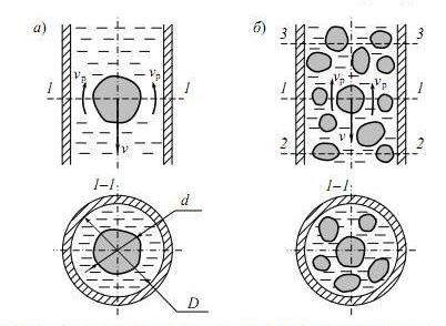
Figure 5.1 - Compressed falling solid particles in a liquid (a) and slurry (б)
Putting the expression (5.2) in equation (5.1) and performing the conversion, find the velocity of the compressed particles fall in the pipe:

(5.3)
ie, the rate of incidence of the particle, the compressed pipe and less than the free fall velocity. However, the difference between these speeds becomes noticeable at comparable particle diameters and pipes. Thus, when ![]() ,when
,when ![]() , e for sufficiently small particles compression pipe and practically does not occur.
, e for sufficiently small particles compression pipe and practically does not occur.
Compressed drop particles in the slurry, due to the mutual influence of the particles, has a similar nature. In this case, the fluid displacement is accomplished not only the particle in question, but also other particles that are in the same section of the pipe, Fig. 3.8 б. Besides, the cross-sectional area free from particles decreases. Therefore, the velocity ![]() will be greater in comparison with the motion of a single particle, thereby reducing the rate of fall of particles v.
will be greater in comparison with the motion of a single particle, thereby reducing the rate of fall of particles v.
Degree of mutual influence of the particles depends on their number in the slurry, ie solids content. A measure of the solid content in the slurry is the concentration - the ratio of the amount (volume or mass) of a volume or weight of the slurry:
(5.4)
where T and P - amount of solid and liquid fractions. If the measure of the amount is the amount - called bulk concentration, if the mass - media.
Distinguish between expenditure and the actual concentration of the slurry.
Flow rate is determined by the slurry concentration dependence (5.4). wherein the calculated amount of the solid and liquid phases that pass per unit time through a pipe section, that is, their consumption in the hydraulic sense of the term. Flow concentration is easily determined and, therefore, has spread in practice. For example, if you know that the installation has a capacity of hydro ![]() m3/h breed, wherein water flow is
m3/h breed, wherein water flow is ![]() m3/h, expenditure concentration can be defined as
m3/h, expenditure concentration can be defined as
(5.5)
For hydrotransport unit operating in the steady state concentration of expenditure will remain unchanged along the entire route hydrotransport.
However, different rates of movement by pipeline solid and liquid phases lead to a mismatch real expenditure concentration ratio of the volume of solid and liquid phases. In the vertical lifting and horizontal lines is a lag of solids from liquids. In vertical down pipe, on the contrary, the solid particles under gravity outperform
fluid.
When photograph
at some point in time the slurry is moving, then the actual concentration of the slurry can be defined as the ratio of the total volume fraction of solid particles between some two pipe sections (section 2 - 2 and 3-3. Fig. 5.1 б) to the volume of the pipe between these sections. Lagging solid fraction from the liquid leads to increase of the actual concentration of the amount depending on the size, density, shape and concentration of solid particles, the diameter of the pipeline and its inclination angle, and from the average velocity of the slurry. Moreover, for the horizontal or inclined pipeline under the action of gravity of the slurry formed nonuniformity over the pipe section : the concentration is greater in the lower section.
For vertical pipe with the slurry from the bottom up the difference between the actual expenditure and concentrations depend on the ratio of the velocity of the slurry and the rate of incidence of compressed particles. The approximate form of this dependence is shown in Fig. 5.2. If the velocity of the slurry significantly higher rate of incidence of the particles in the liquid, and the values of the real expenditure concentrations are almost identical. In the case when these rates are comparable, the actual concentration significantly exceeds the expenditure. A reduction in the pulp below the speed of the fall, it becomes impossible hydrotransport.
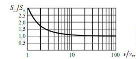
Figure 5.2- Dependence actual slurry concentration on the rate of movement in a vertical pipe
Given the interaction of many particles in the slurry impact, according to [11] the rate of fall in the share was compressed

(5.6)
where n - exponent whose value depends on the concentration of the mixture: if S=0…0,05 – n=1; with S=0,05…0,20 – n=2; when S>0,20 – n>2.
6. Movement of solids in horizontal pipelines
There are two modes of fluid motion : laminar and turbulent. For the first characteristic of the fluid motion in parallel layers, without stirring, Fig. 6.1, while the latter is accompanied by twists and ripple family Instant fluid velocities, Fig. 6.2 б. Laminar motion observed in flows for which the Reynolds number does not exceed 2320 - usually while driving oil and other viscous liquids. In systems hydrotransport turbulent motion is the main form of slurry.
If we consider a point well-established flow in laminar flow magnitude and direction of the instantaneous velocity at this point will be unchanged. In turbulent motion is instantaneous velocity vector is constantly changing both the magnitude and direction. Therefore, in a turbulent flow and always warps the fluid motion in the direction perpendicular to the axis of flow. This movement results in the continuous mixing of the liquid and contributes to the transfer of particulate matter.
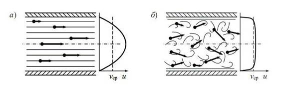
Figure 6.1 - The nature of the fluid and the velocity field in laminar (a) and turbulent (b) modes
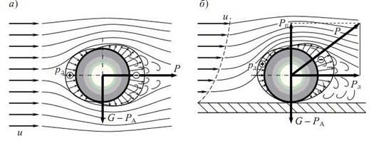
Figure 6.2 - The nature of the flow stream unlimited balls (a) and flow limited wall tube (b)
Weigh solids explained hydrodynamic flow pattern of flow. Consider a horizontal flow wrap spherical body shape. If the body flows about unlimited flow with a uniform velocity distribution, Fig. 6.2 and zones of high and low pressure positioned thereon symmetrically with respect to the direction of fluid motion, and the vector of the resultant force of the hydrodynamic interaction of the body and the flow will be directed horizontally. Lifting force in this case and there is no body under the influence of gravity falls down.
Quite a different picture is observed if the body on the surface bounding the fluid motion, Fig. 6.2 б. This may be the wall of the tube, the bottom of the tray, or a layer on the bottom of the rock mass. Field of the fluid velocity in this case will be uneven approaching speed to a solid surface is reduced. Speed liquid layers are directly on the surface is considerably less than in the middle of flow, see diagrams in Fig. 6.2. Wrapping body becomes asymmetric - the upper portion thereof is streamlined with a higher speed than the lower part, whereby the upper body pressure is smaller than at the bottom. Vector direction of the resultant force will change and the vertical component Рп - ascensional power. If the velocity of the fluid will be sufficient to exceed the value of lift your body weight and it will come off from the bottom.
Depending on the speed of the fluid are four states of the body that is in this thread:
- flow velocity sufficient to move the body from the place: the vertical component Рп hydrodynamic force is less than the weight of the body as well, and the horizontal (frontal force) Рл - is smaller than the frictional force between the body and the surface on which it rests.
- increasing the flow rate of the hydrodynamic force increases; and vertical component is still insufficient to raise body, but the cumulative effect of the horizontal and vertical components of the body moves from place - depending on the form it moves sliding or rolls;
- the flow rate is such that the vertical component of the hydrodynamic force exceeds the weight of the body and lifts it; but when the body falls within the stream where the velocity is less and the uneven wrapping body becomes more symmetrical, the same body has a certain velocity, the lifting force is reduced and the body falls again on the bottom; mode of transportation occurs
jumps
- body lifts flow is transferred to some distance and falls again; - at high speed flow rate of turbulent fluid motion becomes such that the body, being cut off from the bottom, is not returned to him, and transported in suspension.
Hydrotransportation for minerals and rocks is considerable heterogeneity characteristic sizes of particulate matter. Typically, the slurry contains as small dust particles with hydraulic size of a few millimeters per second, and large pieces of rock up to 100 mm and the speed of the fall in the water more than 1 m / s. So at a certain flow rate conditions of transport of the particles forming the slurry, very different.
The movement of the pulp in the conduit has three distinct stages, Fig. 6.3: motion at high speeds ; motion at speeds close to the critical velocity hydrotransportation motion at speeds with a smaller critical.
Movement at high speeds characteristic that is transported with full solid particles without weighing their deposits at the bottom of the pipe, Fig. 6.3 а. In this case, rock particles, more or less uniformly distributed over the pipe section. For a uniform distribution of small particles in the flow occurs at a relatively low speed bones and in the presence of lumpy factions need speed 4...6 m/s or more. These speeds may be economically disadvantageous because of the large pressure losses, and at the same time, the high specific energy consumption.
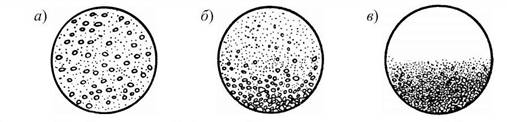
Figure 3.12 - movement slurry through pipes at high speeds (а), at speeds close to the critical (б) and at speeds siltation (в)
Called critical speed hydrotransport lowest average flow velocity at which all solid moves in a suspended state for liquids, a living cross section. Critical rate precedes the onset of the deposition of rock particles size (ie size, which attributed the critical velocity). At a critical velocity head loss will be lowest at the given concentration of the pulp.
Motion at speeds close to critical, there is a concentration of larger particles at the bottom of the pipe, Fig. 6.3 б. Especially large pieces move irregular
or roll on the pipe wall. Since the rock particles are distributed unevenly over the pipe section, in which case the slurry can not be regarded as homogeneous.
At low speeds the rock particles begin to fall to the bottom of the pipe and formed their deposition, Fig. 6.3. However, in the hydrotransport of such conditions is also possible, since a reduction in the tube cross section due to deposits increases the flow rate, which again reaches the critical.
The value of the critical velocity depends on the particle size hydraulic rock, The critical speed depends on the size of the hydraulic rock particles transported, grain material composition, its density, and other properties of the pulp concentration and the diameter of the pipe. Since the process of transporting the solid horizontal fluid flow is complex and due to several factors, find dependencies that would adequately describe it analytically very difficult. So have spread calculation method parameters hydrotransport (critical velocity head loss) based on empirical or semi-empirical formulas. Typically, such methods are based on experiments and have certain limitations in use. There are many such techniques (A. S. Smoldireva, V. V. Traynisa, Yufin A. P., V. S. Knorozov et al.), Each of which focuses on some theoretical application: transportation of coal, rock, gravel, sand, clay, sill, cement, iron ore, ash, etc.
7. Airlift-dredge complexes
Airlift-dredge complexes is a specific means of hydraulic mining, in which the rise in soil intermediate container provided airlift and carries soil pump pumping slurry map reclamation or to the consumer. Airlift-dredge complexes (ADC), compared with traditional dredgers have higher productivity, less labor and cost of production, provide an opportunity to develop resources at a depth of several hundred meters, including under a layer of rocks, and work -pound pump constant high concentration pulp.
Airlift used for lifting the bottom of the pond the solid (e.g., airlift ADC) can be operated with high efficiency, with an efficiency comparable centrifugal pumps - up to 60... 75% [12]. In this airlift has some undoubted advantages, the main one being - simplicity and reliability, the ability to transport slurries with high solids concentration - up to 35... 40%. (coal pumps and ground pumps, according to manufacturer's operating instructions, deal with a concentration of 10 %). Airlift has no moving or wearing parts, does not require constant monitoring and maintenance as required by the compactor centrifugal pump, simple and inexpensive to manufacture.
Airlift is not afraid of emergencies, fatal
for pump installations: can transport the rock mass containing large pieces of trash, metal objects, works even if the dredge littered with rock mass. Airlift creates high pressure in the riser, simple and safe maintenance.
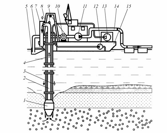
Figure 7.1 – airlift-dredge complex. 1 - dredge with mixer tap; 2 - lift pipe; 3 - air supply pipe; 4 - pipe supplying water to scour; 5 - intermediate vessel; 6 groundwater pump suction pipe; 7 - Blow-off column; 8 - an air; 9 - Block; 10 - winch; 11 - groundwater pump; 12 - booster pump; 13 - compressor; 14 - Pressure slurry pipeline; 15 - the case
Airlift-dredge complex mounted on the housing 15 serial dredger (Figure 7.1), average dredge which is replaced by the airlift, consisting of dredge mixer 1, 2, and the air lift tube and air separator 3, an air 8, pump 12 clean seawater on line 4 is fed into the suction nozzle 1 device that provides soil erosion and fluffing. The slurry is supplied to the mixer, combined structurally with the suction device 1, where it mixes with the compressed air supplied by the compressor to the mixer 13 through the duct 3. Aero slurry is formed by three-phase riser 2 rises in the air separator 8, where it is separated into two phases: the air is directed into the atmosphere, and the pulp is drained by relief column 7 in the intermediate vessel 5. last pulp is diluted to a concentration of seawater needed to pump it groundwater pump. Of the intermediate container 11 groundwater pump pulp is pumped through a slurry pipeline 14 map alluvium.
Deepening dredge performed by lowering total composition airlift (lift 2, 3 and air supply pipe working water 4) winch 10. Becoming designed as a long sections 2.5...3 m, which are connected by means of flanges.
The suction unit and mixer tap, which are equipped with airlift-dredge complexes, in most cases carried out constructively together on one site, Fig. 7.2. Erosion of the settled solid material is carried nozzles 7 fed by water which is supplied to the manifold 6 through a pipe under pressure from a special pump 5. Compressed air is supplied through pipe 2 into the chamber of the mixer 3 where gets in through holes riser 1, where it is mixed with pulp, which is sucked into the pipe 1.
Blow-off column 7, Fig. 7.1. provides an intermediate descent pulp container and remove residual air. 8 an air moves in a vertical slot in the column cowling. Interim capacity 5 designed to regulate the concentration of solids in the slurry is pumped groundwater pump. Capacitance connected with joint watercraft 15 and one with a winch rope rises above or falls below the level of sea water for the purpose of diluting the pulp to the concentration required for pumping slurry groundwater pump.
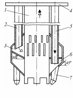
Figure 7.2 - dredge airlift-dredge complex, combined with mixer: 1 - lift pipe; 2 - air supply pipe; 3 - mixer; 4 - flange; 5 - supply pipe and water erosion; 6 - ring collector; 7 - hydraulic head opener
Conclusion
Airlift-dredge complex (ADC), compared with traditional dredgers have higher productivity, less labor and cost of production, provide the possible development of resources at depths of several hundred meters, including under a layer of rocks and soil pump work constant high pulp concentration.
Airlift is not moving or is quickly wear out, does not require constant supervision and I care, as required by the centrifugal pump groundwater, and simple and inexpensive to manufacture.
Operating experience airlift-dredge complexes extracting sand from rivers and reservoirs showed their exceptional advantages over conventional dredge. Despite a few (about 20%) greater consumption of electricity or diesel fuel, the cost of the extracted material is lower than for the dredge, due to the higher concentration of the resulting slurry, stable and trouble-free operation of the complex. In addition, the complex has many times greater depth development - up to 120 m, which allows them to be in such an environment in which ordinary dredger is not able to work. Have experience operating airlift-dredge complex in winter conditions, as well as its location in an extremely small in depth and space reservoir (wading conditions). In airlift-dredge complex provides a positive work environment for groundwater pump, which is fed with slurry prepared constantly high concentration, which does not contain a large piece ; pump operates with a small vacuum in the intake manifold, which significantly reduces the probability of working in a cavitation mode.
Given the advantages of airlift-dredge complex, it is advisable to use it to clean the sludge from the bottom of the inland waters, instead of the dredger.
In writing this essay master's work is not yet complete. Final completion: December 2014. Full text of the work and materials on the topic can be obtained from the author or his manager after that date.
References
- Гейер В. Г.; Логвинов Н. Г. О свойствах безразмерных характеристик эрлифтов // В кн.: Разработка месторождений полезных ископаемых. - Киев: Техника. 1979, вып. 31
- Малеев В. Б. Исследование и разработка сифонно-вакуумного эрлифта для очистки шахтных водоотливных емкостей. Автореф. дисс. канд. техн. наук. — Донецк: ДПИ, 1980. -20с
- Усков Е. В. Исследование эрлифтов для средств водоотлива из глубоких шахт. Автореф. дисс. канд. техн. наук. - Донецк: ДПИ, 1972. -20с
- Венинов В. А. Теория подобия и моделирования применительно к задачам теплоэнергетики. Изд. «Высшая школа», М.,1966.
- Козыряцкий Л. Н. Моделирование и критерии подобия эрлифтов. Депонирована в ЦНИЭИуголь, № 407, 975.
- Костанда В. С. Экспериментальные исследования эрлифта с переменным альфа и С в условиях откачки ствола. Труды ДПИ, том 62, выл 12,1961
- Костанда В. С. О кинематической структуре водовоздушной смеси в эрлифте. Труды ДПИ, том 62, вып. 12, 1961.
- Гейер В. Г. Водоотлив в глубоких шахтах. - В кв.: Разработка угольных месторождений на больших глубинах (Труды совещания в Донецке), Углетехиздат, 1955.
- Мойсис, Гриффитс. Влияние входных условий на снарядный режим течения двухфазной смеси // труды американского общества инженеров механиков, серия С. Теплопередача. – Том 84. -1962. -№1
- Уоллис Г. Одномерные двухфазные течения. – М.: Мир, 1972. -440с.
- Заря А. Н. Исследование образования закупорок в трубопроводе при выключении вуглесоса. Труды ДПИ, том 62, 1961.
- Козыряцкий Л. Н., Федоров О. В. Коэффициент полезного действия гидравлических подъемных установок // Наукові праці ДонНТУ. Випуск 123, серія гірничо-електромеханічна. – Донецьк: ДонНТУ, 2005.