
Abstract
Сontents
- Introduction
- 1. Theme urgency
- 2. Goal and tasks of the research
- 3. Methodology of research
- 4. Calculation of loading scheme efforts
- 5. Metal construction installation
- Conclusion
- References
Introduction
Creating a means of complex mechanization increased , compared with the existing , installed power is a common scientific and technical direction of the industry .
Higher maximum torque of the motor for causing a corresponding increase in theoretical capacity combines, within the limited dimensions of the machine height , causes an increase of loading gear executive bodies and difficult issues to ensure the required reliability elements gears . Insufficient , in some cases , load capacity gears shearers by bending constrains the use of electric drive with high specific power . Bearing capacity transmission is therefore one of the possible reserves increase machine productivity.
1. Theme urgency
Despite the large volume of studies on improving gear , the issue of increasing the bearing capacity and durability of the gears shearers is very important.
In all coal basins in the country's principle sources of the spread of high- lavas got shearers with screw executive. Combines with screw executive bodies represent approximately 90 % of all vehicles produced Gorlovskaya Machine-Building Plant . Kirov to work with lavas gently falling layers .
Application working body screw type caused a number of design features of multi- gear shearers and their gear . Construction analysis gear combines with screw executive bodies , as well as consideration of scientific papers on research shows that the lack of necessary volume of experimental data on the uneven stress distribution across the width of toothing and relevant theoretical generalizations are not allowed , in some cases , enough justification to accept the parameters of the longitudinal surface modification of gear teeth . Kink gear teeth shearers is the most dangerous type of injury , since it leads to crash cars and prolonged shutdowns of coal extraction process . Long as a break from work because of high lava combine accident causes a decrease in coal production for hundreds of thousands of tons . One of the main reasons most of the damage gears shearers including kink is to focus on the load of the tooth caused by inaccuracies in the manufacture of gears and body parts , deformation under load transmission elements , as well as the lack of rigidity of the latter. This work is devoted to solving a number of issues related to the creation of high-performance and reliable in the shearers with screw executive bodies[1].
Picture 1 - The process of coal shearer (animation: 9 frames, 5 cycles of repetition, 115 kilobytes).
2. Goal and tasks of the research
The aim of this work is the development of theory and methods of rational choice of parameters modification longitudinal gear teeth spur wheels shearers with screw executive bodies that reduce the maximum bending stress and causing the possibility of increasing available power and performance of the machine .
To ensure the goal in the work required to do the following :
1. Study variables and the distribution of bending stresses in the teeth of gear wheels commercially available shearers during loading of drive elements of the executive bodies close to the production and comparison with calculated by existing methods .
2 . Examination of character changes bending stresses on the transition surfaces of the teeth during meshing tooth pair at different levels of loading gear.
3 . Development of procedures for the selection of rational parameters of longitudinal tooth modification and its experimental verification[2].
3. Methodology of research
Methods of determining the maximum stress on the transition surfaces of the teeth during their engagement and study of stress distribution across the width of toothing was as follows :
1. Reducers executive bodies combines manned " measuring " the gears on the teeth which in several sections across the width of the danger zone on the curve of the transition surface on the side of the compression strain elements were pasted .
2 . On special bench installations simulated loading drive combines elements close to the level of loading in the field. The studies were conducted at several diagrams on the operation of machines , differing in the machine's height and packs coal destroyed lagging auger.
3 . Investigations were carried out at several levels of loading transmissions.
Maximum load level corresponded full use of the potential of the motor.
4. Maximum stress on the transition surfaces of the teeth were determined by strain measurement when turning "measuring" tooth pair at a constant rate throughout the entire cycle of engagement.
5. Registration units simultaneously produce moments of resistance forces drives the executive bodies and to record the angular displacement of one of the elements under study transmission[3].
The main feature of the methodology is to simulate in the laboratory production of loading drives at various circuits of the machines that made ??it possible in studies of stress state accounting of all real strain nodes gearboxes. Because of the low stiffness movable joints, and as a result the deformation supports, and other parts of the shafts takes place in some cases a significant distortion in the plane of the engagement tooth, which is defined not only by the efforts in engagement, but also the load caused by a cantilever arrangement of actuators , moving mechanism, supports combine on the conveyor, etc[4].
4. Calculation of loading scheme efforts
External loads were simulated by considering the efforts on the incisors of the executive bodies blasted by slaughter. When simulating the loaded condition of gear groups combine screw-type spatial system efforts on the executive board was replaced by a force applied auger . The magnitude and location of this force in the space create moments of resistance forces in relation to one of the ends of the screw equal to the corresponding moments , due to the spatial system of forces . Matching condition of loading machine body on the stand when its loading operation has the form
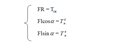
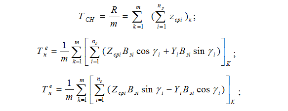
where m - number of the provisions of the screw for his turn; np - number of blades that are simultaneously in contact with the slaughter-in to the position of the screw; Zsrі - the force of i-cutting tool; Yі - force, squeeze the cutter from the bottom; Bzі - distance of i-cutter from "dammed" end of the screw; ?і - angle defining the position of i-cutter on the circumference of the screw.
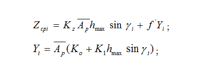
where Kz - integral coefficient taking into account the effect of brittle-plastic properties of coal , its spin outcrop face , the angles of the incisors, the average width of the cut on the cutting force at a certain scheme set incisors and the selected tool ; Ar - resistance to coal cutting neotzhatoy area array ; hmax - maximum thickness of the slice ; f'- cutting resistance coefficient ; Ko, K1 coefficients taking into account the effect of slice thickness , respectively, and resistance to coal cutting force , squeeze the cutter from the face. Calculation of parameters of loading drive F, l and ? to simulate loading of operational conditions of the combine was made full use of the energy potential of the drive. Initial data were coal resistance to cutting of Art and received the results of experimental investigation of the stability of the motor[5].
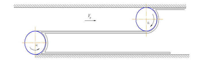
а).
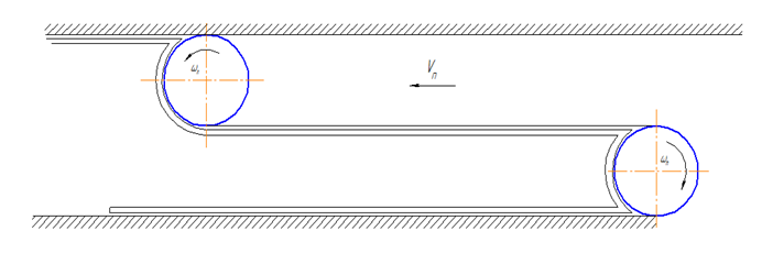
b).
Picture 1 - Scheme of work shearers CGS-13 in a different direction Vn
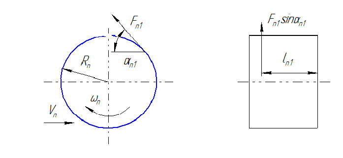
Picture 2 - Right loading auger 13 at the CGS combine his work on the scheme a)
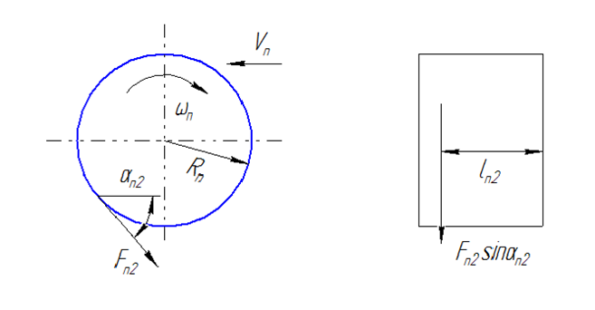
Picture 3 - Right loading auger 13 at the CGS combine his work on the scheme b)
5. Metal construction installation
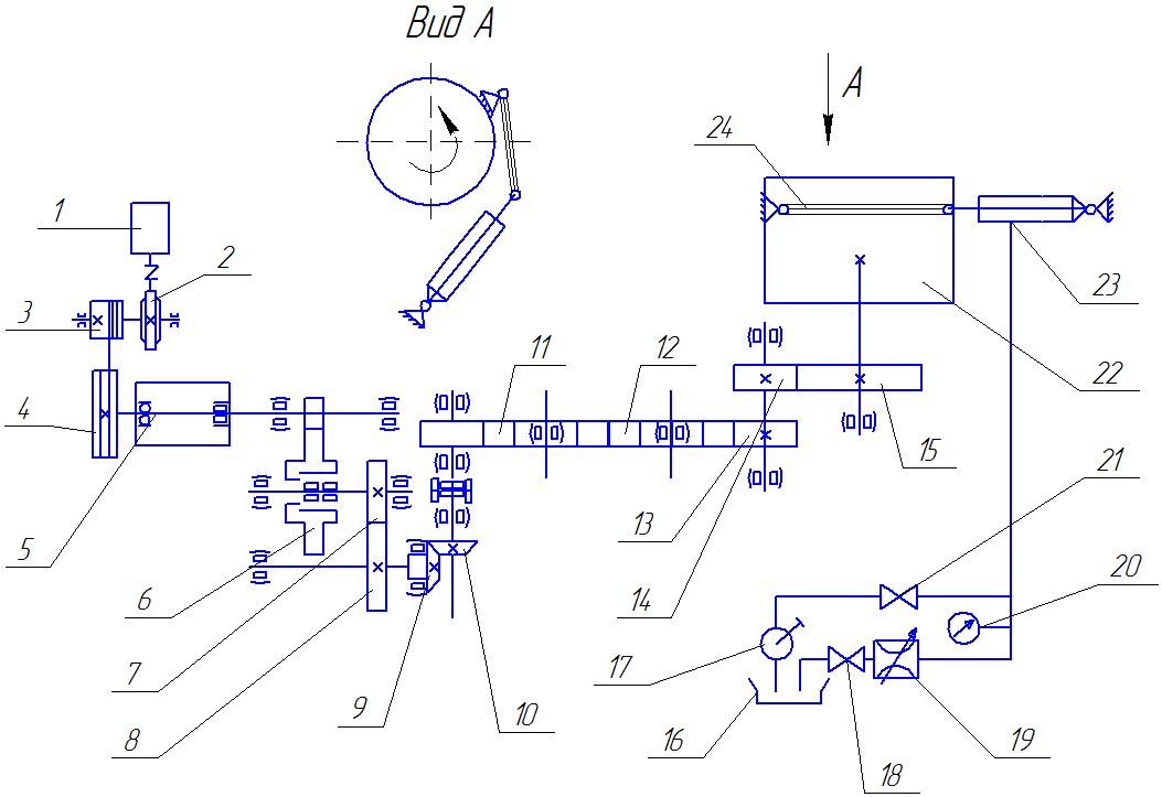
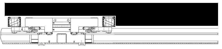
Picture 4 - Diagram of the bench set for research gears combine CGS 13.
Schematic diagram of the bench set for research gears combine RKU13 presented in Figure 4 . Main element of the plant is full-scale specimen drive executive body combine with the attached motor. Attachment method eliminates distortion motors real strains in external loads . Supporting skis combine rely n6a section panline lying freely on the basis of the stand , which corresponds to the actual operation of the machine. Is driven by the electric motor, which through the worm gear using drum unwinds cable pulley rigidly located on the motor shaft , and provides the rotation of the first shaft gear . Load on the executive board , simulating resistance from the blasted coal creates hydraulic jack , the stock chain which connects to the screw so that ensured the constancy of inclination with respect to the hydraulic jack screw in the process of turning . Depending on the fixing screw runs giidrodomkrat either tensile or compressive , thereby providing various circuits auger taking place during operation.
When tension or compression rod of the hydraulic jack or its piston rod end is squeezed oil which is discharged through the hoses in an oil bath , load on the actuator body is caused by the passage resistance of fluid through an orifice that provides the ability to control the force of the jack . Control is carried out on the pressure gauge and deflection of recording the corresponding value on the oscilloscope screen .
Return jack of the loading system and the entire powertrain to its original position at the end of each loading cycle is carried out pump, which pumps oil from Vanny in a corresponding cavity hydraulic jack . Return system conducted at the disconnected coupling connecting gear to the motor shaft . Cranes are used for changing the direction of fluid flow . When the engine hoist and create the required resistance to the screw using the whole load transmission device rotates under load[6].
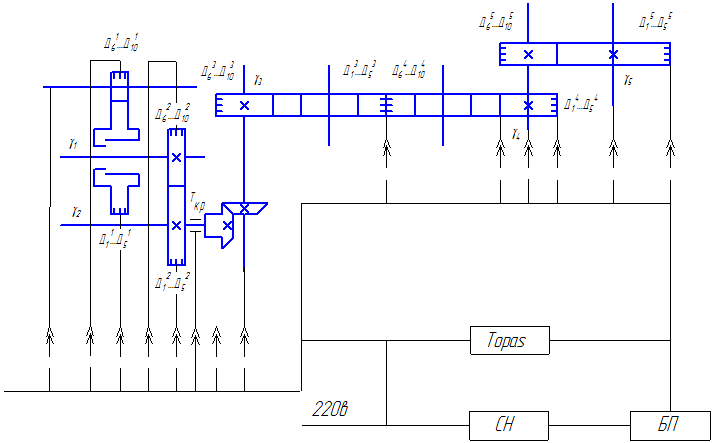
Picture 5 - Diagram measurements studies gears combine CGS 13.
Scheme bench measurements in studies of spur gears harvester RKU13 are presented in Figure 5. According to the procedure of research on measurements of voltage transients produced by surfaces of the teeth successively for all test pairs . In order to determine the stress distribution across the width of toothing "measuring teeth " equipped with strain gauges glued five along the tooth. In Figure 2 shows the installation location for the strain gages on " measuring the teeth ." To measure the relative angular displacement angle sensors used . Voltage stabilization in power supplies power supply equipment produced voltage stabilizer SN.Registratsiya measured quantities produced twelve- light registrator Topas.
Conclusion
The technique operedeleniya maximum stress on transition surfaces of the teeth and their distribution across the width of the ring gear spur wheels shearers during the cycle linking pairs of teeth.
Substantiated loading scheme drives the executive bodies of screw type , allowing a sufficient degree of accuracy in the laboratory to simulate loading driving elements taking place in the field.
On the basis of full-scale models of drives executive bodies combine RKU13 were created bench installation, providing the opportunity to simulate the loading of the elements of the transmission machinery harvesters at work in such circumstances.
Design bench installations and applied instrumentation allow registration of maximum stress on transition surfaces in different sections on Shireen all gears spur gear during harvesting cycle engagement tooth pair at different loading of it.
References
- Повышение производительности и долговечности угледобывающих комбайнов. Донецк,1974, 212с
- Заблонский К.И. Жесткость зубчатых передач.Киев,"Техника",1967, 259с.
- Кудрявцев В.Н. Зубчатые передачи.М.-Л. Машгиз,1957, 263с.
- Устиненко В.Л. Напряженное состояние зубьев цилиндрических прямозубых колес.М.,"Машиностроение",1970, 89с.
- Комбайны очистные,выбор параметров и расчет сил резания и подачи на исполнительных органах.ОСТ 12.47.001.-73М,184с.
- Брюшин Н.В. Снижение максимальных напряжений изгиба в зубьях цилиндрических прямозубых колес очистных комбайнов со шнековыми исполнительными органами:диссертация,Донецк,1978, 198с.
- Передачи зубчатые цилиндрические эвольвентные.Расчет на прочность ГОСТ 21534-75М.,1976, 61с