
Abstract
Contents
- Introduction
- 1 History monorail
- 2 Actuality of theme
- 3 Mathematical model of movement
- Conclusions
- References
Introduction
Nowadays, in the developed countries is very widely used suspended monorail transport. With his help solve the problems above–ground isolation of traffic. Foreign and domestic experience has shown successful results in the application of of monorail transport not only as overhead, but also as an underground. When operating in the mine of monorail transport problems are resolved or simplified to transport people and support materials to develop. A particular advantage is the practicality of use and safety.
There are two monorail system: the cable car and locomotive traction. Of these, preference should be given to the second as it provides a very high safety. Also, when using roads with cable traction problems arise opportunities to work on branched lines and long–haul transport.
In our time, began to actively innovate to ensure safe operation of miners. The introduction of light rail transport has allowed to reduce the amount of manual labor haul jobs, reduce injuries associated with congestion, tow hitch rolling stock maneuvers on turnout, the cliffs of the rope, a gathering of transport vessels to the track, to solve the problem of delivering people to the place of work and back to to the surface. From the movement of people in mine workings monorail, subject to a clear timetable for delivery, now working there is no need to walk or ride on vehicles that are not designed to carry people. Application monorail locomotive in mounting cameras allowed to reduce the time and reduce the complexity of installation and dismantling.
The Monorail – a transport system in which cars move along the beam monorail–mounted on separate poles or overpass. However, this definition is too vague. Really monorails are divided into a number of very specific varieties, the total between them – only monorail.
1. History monorail
First monorail in the world was in 1820 in Russia. Then the villager Myachkovo in Moscow Ivan Elman built the "road on pillars" – the top of rail rolling trolley pulled by a horse. A little later, regardless of the Russian inventor, monorail similar design was invented in the UK by Henry Robinson Palmer. He patented his invention of November 22, 1821. In 1824, the UK was built the first functioning monorail. It was used at the naval shipyard solely for the carriage of goods. The first passenger monorail in the world was opened June 25, 1825.
After doing this for about half a century, is nothing new in the field of building monorail happened. Attempts to create a workable monorail, now steam–powered, resumed at the end of XIX century. It is known that in 1872, at the Polytechnic Exhibition in Moscow demonstrated the monorail station design engineer Lyarsky.
So at the end of XIX century, the monorail was a frequent guest on variety shows. In 1872, the monorail on the cable–drawn demonstrated in Lyon, 1891 in St. Louis demonstrated monorail with cars like the tram.
At the same time, the creation of effective, workable monorail was much more difficult. In the XIX century there was a huge number of designs created by the monorail, but most of them have remained on paper, and those that have been implemented, did not differ longevity. In 1878, began to operate steam monorail connecting Bradford and Gilmore (PA). Its length is 6.4 km. This monorail was created for transportation of industrial equipment, but it also carried passengers. Bradfordsky monorail was closed shortly after the happened January 27, 1879 a serious accident that killed monorail driver and three passengers.
With the development of electrical engineering at the monorail began to use the electric drive. One of the first electric monorails, known as the Enos Electric Railway, was built in 1887 in Greenville, New Jersey.
As indicated above, despite an active search, a monorail that can be a full vehicle in the XIX century and failed. The only successful monorail that era – built in Ireland in 1888, a monorail connecting the Ballibunion and Listowel. It existed until 1924. However, the spread of this design is not received.
First monorail horse–drawn were suspended. Steam monorails were kind polupodvesnuyu design: composition relied on the support rail provides lateral stability of the guide rails. Transverse section of the road looked like the letter "A", which corresponds to the highest point of the supporting rail, and the connection point and the sides of the cross bar – guides. With the advent of electric monorails was again used suspension layout.
However offered and more unusual designs. In 1894, the United States was built monorail Boynton Unicycle Railway. On this road train was based on a single carrier rail is held on top of a wooden rail supports. The main drawback of such a road was that bends due to inertia ("centrifugal force") acting on the supporting rail high forces.
At the end of XIX century there supporting monorails. In 1886, the United States was built by experienced this type of monorail, Meigs Monorail, but in those days the spread has not received such a design. Appeared in Captain America Meigs system is composed of two rails, one above the other vertically and supported by metal columns. At the base of this system is the idea of concentrating all the pressure transmitted to the path of the rolling stock, in the center line of the train. Each car is resting on a pair of bogies, supported by two horizontal guide wheels and four–wheel lean, with a wedge–shaped grooves on the rim. The last two rolling tracks of square cross section attached to the bottom chords of lattice girders forming the lower track structure. Horizontal locomotive wheels are, however, for the transfer movement, and because these wheels to increase the pressure, special arrangements are pressed to the rails.
2. Actuality of theme
The theme of the monorails, in particular the locomotives is one of the most common, developing those reports, studies and research in our time. Monorails play an important role in the development of the mining industry around the world. But not all countries can adopt the latest installation in the industry, and the entire system has many flaws. If you do not develop and improve the performance of operation of this type of transport is losing its value, it will be forgotten. A lot of scientists have made the most valuable contribution to the development of light rail transport. Some of them are: Khim. tehn. Science V.S. Bersenev, PhD. tehn. Sciences L.I. Ayzenshtok, A.S. Vetkin, L.G. Zheltukhin, V.N. Grigoriev, V.V. Boukhanovsky other. The most detailed results of research on creating and railcars are in the works of V.S. Berseneva. The main direction of the work of A.S. Vetkina was the research process of inscribing the rolling stock. These patterns can not be used to determine parameters of traction devices, as they relate to the trailing part of the composition. It should be noted that, despite the large number of publications devoted to the establishment and railcars, published in the Soviet and foreign literature, there is no specific methodology to uniquely define the basic parameters of monorails. The first attempts to synthesize these issues belong to V.N. Grigoriev. Based on extensive research they identified the main structural systems of traction devices are defined rational application of monorails, issues influence the design features monorail locomotive motion parameters of a possible train speed and sufficient capacity of the locomotive, as well as the method of controlling the drive.
3 Mathematical model of movement
Let's study the crew plane motion consisting of material particle of mass and imponderable bar of length  ,on which one this particle is suspended, in the field of gravity. With this, suspension point isn't fixed and can move along some (given or chosen) trajectory. It is supposed the absence of any friction and resistance forces. The crew position will be determined by angle
  . Let's give some position
  in which it is situated at initial time with zero angular speed. The task is to find the law of motion of suspension centre
  , which does not allow crew to change the position with time, i.e. to provide the solution existence
  .
.
Motion equation (fig. 1) at suspension centre motion by law  is
is
 (1)
(1)
The important particular case appears when suspension centre oscillates along some axis forming angle with the gravity direction. Having marked the suspension centre displacement along this axis  ,we have
.jpg) (2)
(2)
and crew oscillations equation (1) turns into
 (3)
(3)
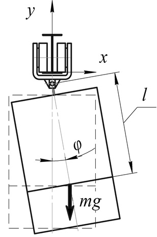
Fig. 1. Design diagram of crew motion
As upper  and lower
  crew verticals are equilibrium positions at fixed suspension
  , so let's delete them from further studying and let's suppose that
  . Let's only mention that for keeping vertical positions of crew equilibrium the suspension centre can move only along the Oy. As it is followed from [4], upper position becomes stable at suspension oscillations along the vertical with the frequency higher than
  , where
  – amplitude of these oscillations.
Let's find out such suspension centre motion as  . Functions x(t) and y(t) can be regarded as directions in equation (1). As class of permissible directions let's study continuous twice differentiable functions. So taking into account
  the equation (1) let's turn into
Whence
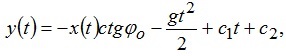 (4)
(4)
where  - some constants which are determined from initial values of speed and position of crew suspension.
Have chosen x(t) in random way from the class of permissible directions from (4) we'll get y(t), have determined in such way suspension centre motion in full. Thereby we have family of directions x(t), y(t), providing inclined equilibrium of crew. Let's find out if there exist limitable ones among them.
Let it be that x(t) – is limitable on half–interval  function. Then at
  under the limitation x(t) the value
  according to (4) goes to infinity. Therefore the suspension motion at
  can't be limitable at both coordinates. Nevertheless there can be the traffic condition limited at y and unlimited at x, allowing the crew to remain in inclined position
 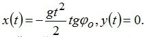 .
.
Let's simplify now suspension motion trajectory. We'll move the suspension centre along the line (2), but let's extend the class of permissible functions . This class will include functions, the first derivatives of which (speeds) can have discontinuities of the first kind in some points at the intervals between these points functions will be as before twice differentiated. In the given points of discontinuity regarded mechanical system will be undergone to pulse action.
Further dependence calculation is described [5], hence we have that at .jpg) sign
sign .jpg) coincides with sign
coincides with sign .jpg) , and at
, and at  – with sign
 .jpg) . These signs are different as it is made an in equation
. These signs are different as it is made an in equation 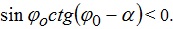 . So under continuous dependence
  on
on  there exists some value
  , at which the speed increase during period T will be zero.
Now let's study increase s(t), it will be  . Obviously that depending on speed initial value
  , we can get different increases
  . Let's choose initial speed in such way that this increase is equated to zero. Let's mark
 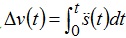 . Then have chosen initial speed equated to,
 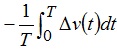 we'll get that increase s(t) will be zero.
Such values of frequency  and initial speed for s(t),that suspension coordinate s(t) and its speed during the period return to initial values. Therefore at these values suspension motion s(t) will be periodic and continuous at t and crew will oscillate relative to position
  by law
 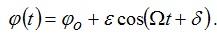 .
.
Let's take the distance from the mass centre point till points of stock suspension =800 long and let's study its horizontal position  . Let it be that axis along which suspension point oscillates angles
 .jpg) with gravity direction. Diagrams of suspension point motion providing harmonic oscillations of tractive equipment at horizontal position with some small amplitude
with gravity direction. Diagrams of suspension point motion providing harmonic oscillations of tractive equipment at horizontal position with some small amplitude  and diagram of frequency dependence
  on at periodic motion s(t) suspension points are shown in fig. 2.
Figure 2 – Oscillations of the crew
(Animation: 4 frames, 8 cycles of repetition, 49,2 kb)
Fig. 3. Suspension motion: a) s=f(t) at  ; b) frequency diagram
  .
.
In the fig. 3b shows a plot of the frequency from at periodic movement s(t) suspension point. From which we see that the frequency  unlimited increases with decreasing amplitude .
Conclusions
Practical value of given work consist in possibility of wider application of monorail transport for odd works in all spheres of transport carriage and increase of speed of crews motion. On the ground of carried analysis of equation of crew oscillations at motion along monorail it follows the biggest influence onto the side declinations is provided by transporting cargo mass, coefficient of stiffness of holding down device and distance from mass centre till suspension points of driven carriage. Another parameters of tractive device and monorail have less considerable influence. There exist periodic by time oscillations of suspension centre at which crew declinations from given fixed inclined position will be as small as is wished.
In writing this essay master's work is not complete. The final version of the work can be obtained from the author or the supervisor after December 2014.
References
- Айзеншток Л.И. Исследование динамики и обоснование параметров конструкции и условий эксплуатации шахтных скоростных монорельсовых дорог: Автореф. дис. Канд. тех. наук. – Днепропетровск, 1983. – 23 с.
- Айзеншток Л.И., Носов В.С., Слободенюк Р.Л. Исследование состояния пути шахтных монорельсовых дорог // Способы и средства безопасной эксплуатации электромеханического оборудования в шахтах. Сб. науч. тр. / МакНИИ. – 1982. – С. 61–62.
- Нос В.С., Айзеншток Л.И. О зазорах в выработках при монорельсовом транспорте // Безопасность труда в промышленности. Сб. науч. тр. / МакНИИ. – 1982. – №2. – С. 47–48.
- Шахтарь П.С. Рудничные составы. – М.: Недра, 1982. – 296 с.
- Фаворин М.В. Моменты инерции тел. – М.: Машиностроение, 1977. – 511 с.
- Капица П.Л. Динамическая устойчивость маятника при колеблющейся точке подвеса // Журн. эксперимент. и теор. физики. – 1951. – 51, № 5. – С. 588–597.
- Капица П.Л. Маятник с вибрирующим подвесом // Успехи физ. наук. – 1951. – 44. –С. 7–20.
- Stephenson A. On a new type of dynamic stability // Mem. and Proc. of the Manchester Literary and Philosophical Soc. – 1908. – 52, № 8. – P. 1–10.
- Stephenson A. On induced stability // Philosophical Magazine. – 1908. – 15. – P. 233–236.
- Стретт Дж.В. Теория звука. – М.: Гос. изд–во технико–теоретической лит., 1955. Т. 1.- 504 с.
- Боголюбов Н.Н. Теория возмущений в нелинейной механике // Сб. тр. Ин–та строител. механики АН УССР. – 1950. – 14. – С. 9–34.
- Крылов H.M., Боголюбов Н.Н. Введение в нелинейную механику. – Киев: Изд–во АН УССР, 1937. – 365 с.
- Боголюбов Н.Н. О некоторых статистических методах в математической физике. –Киев: Изд–во АН УССР, 1945. – 139 с.
- Erdelyi A. Uber die kleinen Schwingungen eines Pendels mit oszillierendem Aufhangepunkt // ZAMM. – 1934. – 14, № 4. – S. 235–247.
- Klotter K., Kotowski G. Uber die Stabilitat der Bewegungen des Pendels mit oszillierendem Aufhangeunkt // Ibid. – 1939. – 19, № 5. – S. 289–296.
- Hirsch P. Das Pendel mit oszilliererndem Aufhangepunkt // Ibi'd. – 1930. – 10, № 1. –S. 41–52.
- Жалким И.Г. Некоторые задачи теории нелинейных колебаний. – М.: Гостехиздат, 1956.- 491 с.
- Блехман И.И. Вибрационная механика. – М.: Наука, 1994. – 400 с.
- Стрижак Т.Г. Методы исследования динамических систем типа "маятник". – Алма– Ата: Наука, 1981. – 253 с.
- Бардин Б.С., Маркеев А.П. Об устойчивости равновесия маятника при вертикальных колебаниях точки подвеса // Прикл. математика и механика. – 1995. – 59, № 6. – С. 922–929.
- Леонов Г.А., Шумафов М.М. Проблемы стабилизации линейных управляемых систем.-СПб.: Изд–во С.-Петербург. ун–та, 2002. – 308 с.
- Сейранян А.А., Сейранян А.П. Об устойчивости перевернутого маятника с вибрирую¬щей точкой подвеса // Прикл. математика и механика. – 2006. – 70, № 5. – С. 835–843.
- Lowenstern E. R. The stabilizing effect of imposed oscillations of high frequency on a dynamical system // Philosoph. Magazine. – 1932. – 8. – P. 458–486.
- Hsu, C.S. On a restricted class of coupled Hill's equations and some applications //J.Appl. Mech. – 1961. – 28. – P. 551–556.
- Холостова О.В. О движениях двойного маятника с вибрирующей точкой подвеса // Изв. РАН. Механика твердого тела. – 2009. – № 2. – С. 25–40.
- Otterbein S. Stabilisierung des n–Pendels und der Indische Seiltrick // Arch. ration. Mech.Analysis – 1982. – 78. – P. 381–393.
- Acheson D.J. A pendulum theorem // Proc. R. Soc. Lond. – 1993. – A443 – P. 239–245.
- Маркеев А.П. О близких к коническим движениях сферического маятника с вибрирующей точкой подвеса // Тр. конф. «Устойчивость и колебания нелинейн. систем упр.». – 1998. – С. 107.
- Петров А.Г. Об уравнениях движения сферического маятника с колеблющейся точкой подвеса // Докл. РАН. – 2005. – 405, № 1. – С. 51–55.
- Маркеев А.П. К теории движения твердого тела с вибрирующим подвесом // Доклады Академии наук. 2009. Т. 427. № 6. С. 771–775.
- Холостова О.В. Исследование устойчивости перманентных вращений Штауде. М. –Ижевск: НИЦ «Регулярная и хаотическая динамика», 2008. – 128 с.
- SMT Scharf [Электронный ресурс] – Режим доступа: http://smtscharf.com/cms/front_content.php?lang=5&idcat=3. Дата обращения 05.11.2012.