
Summary on the theme of master's work
Content
- Introduction
- 1. Topicality
- 2. Research goals and objectives
- 3. Flowsheet object
- 4. Simulation node
- Findings
- List of sources
Introduction
Today it is hard to imagine the city without running vertical transport. For a great many people work normal elevators is synonymous with a normal life.Quality work lifts and hoists and their reliability is one of the key aspects in ensuring the safety of residential and public buildings, so you need continuous development and modernization of the elevator equipment.
Elevator – vertical transport mechanism for transporting passengers and cargo in the residential and industrial areas. The widespread use of electric elevators in industry and everyday life, determines the lift as the most common type of vertical transport.
Observed in the recent trend towards high-rise buildings in the cities, as well as to the comfort of movement in the elevators leads to a complication of process control systems of movement. Thanks to the development of modern microprocessor control systems these tasks successfully solved now.
Modern elevator – is a complex electro-mechanical device that operates in semi-automatic mode for the installed program. The program of work is determined by the actions of the elevator passengers, location and position (vacant or occupied) cockpit and regulated by means of elevator control system.
Elevator control system should solve problems safe and comfortable transportation of passengers [1];. The movement should be realized with acceptable acceleration desired speed and the lack of tangible jerks. To fulfill the above requirements necessary to obtain information about the position and speed of the car by using various sensors.
Much attention should be given to the security of transportation. Also note the use of the control system, not only for the modernization of existing lift equipment, but also the use in new construction.
1. Topicality
Elevator control system should solve problems safe and comfortable transportation of passengers. Movements should be realized with acceptable acceleration desired speed and the lack of tangible jerks. To fulfill the above requirements necessary to obtain information about the position and speed of the car with the help of various sensors and model control system.
Also note the use of the control system, not only for the modernization of existing lift equipment, but also the use in new construction. The topic of the master's work is relevant.
2. Purpose and objectives of the study
The aim of this work is to improve the dynamic characteristics of the elevator control system in transient operating conditions.
To achieve this goal is not necessary to formulate the main objectives of the work:
- Develop a mathematical model of elevator control system based on PID.
- Synthesize a simulation model of the system.
- To investigate the dynamic characteristics of the control system using a mathematical model.
Actual speed measurement is carried out using speed control device UKS-01 [2];. Data processing and issuing control signals to the motor will be produced by a programmable logic controller (PLC).
From reed sensors located on each floor and the surface of the cabin will be monitored processes ramp lift [3];. It will also set the following measuring sensors and instruments:
– Automatic opening and closing of doors BARRIER-1M [4];;
– Temperature sensor;
– Torque sensor;
– Logic module for congestion control cabin CPL 1.1.
To eliminate the emergency on exceeding the maximum load level on the control room panel cabin, and then to the elevator indicator is signaled overload. Exceeding safe speed of the car receives a signal to the PLC, and it assists emergency stop elevator.
3. Flowsheet object
Description of process and equipment
The main parts of the elevator are: winch, cab, counterweight guides for car and counterweight, landing doors, speed limiter, traction ropes and rope speed limiter, components and parts of the pit, electrical and Electricity. The main technical parameters of the lift characteristics: rated load m = 400 kg. Counterweight mco. = 1000 kg, the mass of the empty cabin m0 = 800 kg, rated speed U = 1 m/s. Elevator twelve-story building plus floor maintenance. 3 m distance between floors. Estimated drive is starting every 3 minutes, 20 times per hour.
Figure 1 – Diagram of the elevator
Kinematic diagram of the elevator is shown in Fig. 1.1. Elevator has sheave block suspension hoist multiplicity 2 at which the traction ropes 1, coming off the sheave 2, block 3 sheave block skirts on the cab and counterweight 4 and 5 are attached to the upper part of the shaft in the engine room.
Move the car and counterweight guides carried by 6 winch installed in the engine room by a traction rope 1. Ibid posted speed limit, the controller, the input device. Lift completed specialized controller.
Pressing the ring apparatus in the elevator control electrical equipment supplied electrical impulse (call). If the car is at a stop, from which the call came, opened the cab door and mine at this stop. If the car elsewhere, the command to its motion. In the motor winding winch and electromagnetic brakes coil is energized, the brake is released, and the rotor of the motor is in motion.
When approaching the cabin to the desired landing site elevator control system signal sensors exact stop switches winch motor to work with low rotor speed. Speed of the car is reduced, the command to stop, and when the threshold level is combined with the cockpit door sill mines, car stops, the brake shall be included in the work of the drive door and car door and open the mine. The elevator control system with the controller occurs infinitely variable rotor speed motor through the frequency control system that ensures smooth stop and start the cab.
When you click the order on the control panel located in the cockpit, cabin doors are closed and mine, cabin sent to the landing pad, which pressed the button order.
After arriving at the desired landing area and passengers exit doors are closed, the cabin stands up until the button is not pressed any ring system.
The cab is only possible when all the serviceability of the locking and safety devices. Actuation of any safety device results in the opening of the control circuit and stop the cab.
The design of the elevator lift mechanism based on the use of the cable winch system transmitting motion cockpit.
Passengers moved to a specially-equipped cockpit with closable doors that have locking devices, excluding the possibility of movement when opening gate.
To center the car and counterweight in the horizontal plane and transverse swinging during movement used rails installed on the entire height of the elevator shaft.
Guides allow braking cabin (counterweight) catchers in emergency overspeed and hold it until disarming the catchers.
Space in which moves shielded cabin and counterweight to full height and is called the shaft.
The room in which you install hoisting winch and other necessary equipment, called a machine room.
Part of the mine, located below the bottom of the landing area, forming a pit, which houses stops or buffers, limiting move cabins (counterweight) down and stopping with the allowable acceleration deceleration.
For the prevention of accidental fall of the cab (counterweight) elevator equipped automatic inclusion catchers from the speed limiter is triggered when an emergency overspeed.
Catcher installed on the sides of the chassis cab (counterweight) and driven rope covering pulley speed limiter.
In the pit set tensioner speed limiter.
Lift station control operation, devices and apparatus are in the machine room.
Connect electrical equipment cabin with control station is provided by the suspended cable and harness mounted in the shaft.
Sensors deceleration sensor shunts exact stop and control devices shaft doors are also installed in the mine.
Fig. 1.1 shows the layout of the elevator equipment. Winch and control box located in the elevator room, closed-intrusion.
Figure 1.1 – Flow diagram of equipment
The baseboard management controller installed in the cabinet. Serial data line is divided into channels cabin and mine. Channel cabin, which is connected to the terminal box cab is a hanging cable. Fig. 1.1 the following notation: 1 – cupboard controller, 2 – position indicator, 3 – storey buttons, 4 – position sensor cab.
4. Simulation node
Preparation of a mathematical model of the induction motor, the underlying operation of the elevator, is the basis of general object model. From the known motor nameplate data series 4 A [5];5.5 kW make the following necessary calculations:
Rated phase stator current:
Reference value of resistance:
![]() Ом
Ом
Angular frequency of the current:
![]()
Stator leakage reactance in relative units:

Factor binding machine parameters in T and L-shaped equivalent circuits [6];:
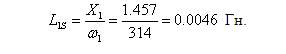
Leakage reactance of the stator phases:
Resistance of stator phase:

Leakage inductance of the stator phase:
Leakage reactance of the rotor phase:

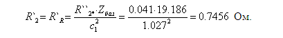
Resistance of the rotor phase:
Phase leakage inductance of the rotor:

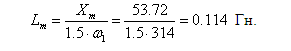
The mutual reactance:

The mutual inductance:
Simulation model of elevator control speed is shown in Figure 1:
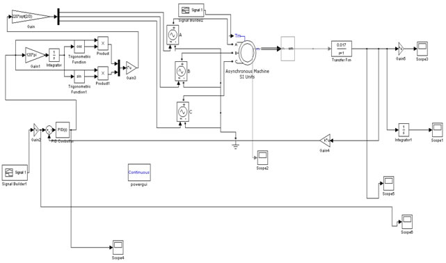
Figure 1 – Simulation model of elevator control speed
To maintain speed down the PID-choose the most effective and common form of control, which provides sufficient accuracy in the management of various processes [7]. It is known that this control should be chosen for control systems with relatively low noise level and the amount of delay in the control object.
For controller synthesis method is applicable Ziegler-Nichols [8];.
- Expose all coefficients (Kp, Ki, Kd) to 0.
- Begin gradually increase the value of Kp and monitor the response of the system. We need to ensure that the system began in sustained oscillations (caused by deregulation). Increase Kp, while vibrations of the system to stabilize (stop decay). Remember the current value of Kp (denote it Ku) and measure the period of oscillation of the system (Tu). According to the results Kp = 52, Tu = 0.9.
- Now use the obtained values of Ku and Tu to calculate all parameters of PID controller according to the formulas:
Kp = 0.6 * Ku; Kp = 31,2
Ki = 2 * Kp / Tu; Ki = 69,3
Kd = Kp * Tu / 8; Kd = 3,51
These settings substitute PID and promodeliruem system and evaluate the results [9].
Consider the following variant movements, stops the elevator: lift is on the 3rd floor, it comes to one person, the destination floor – 5.
The simulation results are presented below in the animation 1:
Аnimation 1 – Graphs of the control current line speed of the lift, the moment of resistance, moving cab
Conclusions
ACS was designed process control movement of the elevator car. We analyzed the process of the object, its flow chart and the design goal of ACS. Were identified tasks required by the system to achieve this goal.
Were obtained and analyzed transients data models. Moment of resistance and control current signal varies under different conditions, but the graphs shows that the impact is fulfilled and set the output we get the desired speed with minimal deviations from the specified values of the input.
In the future, the system will be made to non-linearity [10] and will be explained the best way of their mining to achieve this goal.
List of sources
- П. Д. Гаврилов, Л. Я. Гимельштейн, А. Е. Медведев Автоматизация производственных процессов – М.: Недра, 1985. – 216с.
- Сайт компании
OTIS
http://www.otis.com. - Под общ. ред. И. П. Копылова и Б. К. Клонова Справочник по электрическим машинам: В 2т./С74. Т.1.–М.: Энергоатомиздат, 1988. 456 с.
- Электронный каталог лифтового оборудования. http://лифтов.рф/liftovoe-oborudovanie-katalog.
- А. Э. Кравчик, М. М. Шлав, В. И. Афонин, Е. А. Соболенская Асинхронные двигатели серии 4А: Справочник/А90 – М.: Энергоиздат, 1982. 504 с.
- В. Е. Китаев, Л. С. Шляпинтох Электротехника с основами промышленной электроники. Учебное пособие для проф.-техн. учебных заведений. Изд. 2–е, переработ. и доп. М.,
Высш. школа
, 1968. 416 c. - С. Г. Герман – Галкин, Компьютерное моделирование полупроводниковых систем в MATLAB 6.0: Учебное пособие – СПб.: Корона принт, 2001. 320 с.
- Ю. Лазарев Моделирование процессов и систем в MATLAB. Учебный курс. – СПб.: Питер; Киев: Издательская группа BHV, 2005. 512 с.
- П. В. Агуров Интерфейсы USB. Практика использования и программирования Спб.: БХВ Петербург, 2004.
- Б. Ван дер Поль. Нелинейная теория электрических колебаний. Пер. с англ. Связьтехиздат, 1935.