
Abstract
Content
- Introduction
- 1. Goals and objectives of development studies
- 2. Analytical review
- 3. Improved water hammer the drill GBS–127m installation UMB–130M
- 4. New technical solutions for improving plant UMB–130M
- Findings
- List of sources
Introduction
The need for further development and expansion of the field of seawater flowsheet many voyage sinking wells to a depth of 50 m, due to the achieved performance indicators drilling geotechnical boreholes settings UMB–130М for hydrocarbon deposits Ukrainian zone areas of the Black and Azov Seas. Compared with the scheme of sinking wells stationary drilling rigs rotary drilling placed on specialized drilling vessels, the use of UMB–130М provides a significant increase in productivity and profitability of the region under consideration offshore drilling production.
Improving the efficiency of penetration is made possible through the use of the combined method of rock destruction. Includes jetting erosion combined with continuous frequency shock loads at the bottom, emerging water hammer mechanism.
The provision of such a method brings new challenges as the development of hydraulic drill hydropercussion the drill installation with increased power output to decrease in the value of drive power and the rationale and design parameters launchers nodes providing permanent job hammers during the entire cycle of penetration with a fast and reliable unlocking mechanism in the selection of the core.
Further improvement of hydropercussion the drill further provides solution to the problem of processing engine of hydraulic mechanism with efficient performance of his work at a flow rate of 200–220 l/min and pressures up to 3.5 MPa. Such indicators may be a factor in the drive not only reduce the hydraulic load in the hydraulic drive with software defined indicators frequency power parameters hydropercussion machine but also a condition of obtaining new choices of parameters and control modes launchers nodes[1, 4].
Communication with academic programs and plans of work on applications of scientific or industrial organizations.
1. Goals and objectives of development studies
Purpose–to achieve a new level of efficiency installation UMB–130М by increasing impact power hydropercussion the drill with the simultaneous implementation method of destruction of rocks on the range full-hole drilling, based on the use of jetting effect in combination with continuous frequency shock loads on the face.
Tasks, foreseen in the master's thesis considered as part of studies in accordance with the scientific direction of the department Geological Prospecting Engineering, and deal with improving technology and engineering geotechnical drilling wells offshore.
Hydropercussion the drill provides a solution to improvement of problem:
- Analysis concepts hydropercussion drill comprising installations of UMB and their combined features ensure the destruction of rocks at intervals wells.
- Rationale and development of design parameters of hydraulic drill with high-frequency power characteristics.
- Select a scheme, the rationale and development of design parameters starting nodes in the structure of hydropercussion the drill.
Object of study – technical and technological schemes of the trip many geotechnical drilling wells offshore.
Subject of research – Hydroshock drill and methods of their optimization for conditions mnogoreysovogo drilling offshore.
Possible outcomes, that are expected as a result of their work, their novelty and significance-operating system documentation water hammer the drill-starting nodes
recommendations to the choice of control parameters launchers nodes at intervals combined destruction of rocks along the wellbore.
Planned testing results: participation in student conferences with the publication of abstracts; Preparation work for the competition of student works; participation in international scientific conferences; publication of articles in scientific journals.
2. Analytical review
Area offshore drilling is actively developing, so we have a number of GBS developed counterparts. Have now been developed and widely used shells GBS–127 installation UMB–130–108 GBS installation UMB-130M, GBS127–2M installation UMB-130, capable of performing drilling mnogoreysovoe out across vertical cut wells soil any consistency related to I category-IV on drilling capacity to a depth of 6-25 m from the board of specialized courts. In developed multifunctional drill, except compulsory dives core set into the ground and create a reverse circulation of fluid in the core tube, provided the opportunity to scour the surface of the borehole walls along the core set. This creates the conditions under which immersion and extraction BSS made ??without a significant impact on efforts friction contact surface rocks with drifter set[1, 4].
3. Improved water hammer the drill GBS–127M installation UMB–130M
In order to improve the operational reliability of the mode is changed in the process of hammers combined process of destruction of rocks on the intervals of the well. Technical prerequisite for the task were the successful operation of the accumulated data of the lower trigger assembly GBS–127. With this as an acceptable solution to the issue objectively processing start the upper valve accepted unification condition (relative to the start the lower valve ) design and character changes his position and stop-regulating system (by increasing or decreasing the flow of fluid in the hydraulic system).
In the process of carrying out these works are having difficulties caused by the choice of design elements and layout start the upper valve GBS structure and compliance with the conditions of the synchronous triggering of the stop and control system lower and upper launchers nodes in the range of nominal liquid flow to work effectively hammers and erosion of rocks at the intervals of the well[7, 8].
When relations between the parameters laid down mechanism of hydraulic motor GBS–127 values of impact energy and impact frequency and destruction, primarily found in the section of the wellbore sawmills, provided at a flow rate 340–350 l/min and a system pressure of 3,5–4,5 MPa.
To operate lower starting node (conditions of adequacy erosion of rocks on the interval of the well , taking into account technical constraints drive), the magnitude of the desired amount of liquid is 400–420 l/min. To ensure a steady state phase at upper launcher assembly coring intervals quantitative excess liquid flow 60...70 l/min is quite difficult and not always possible, even in the laboratory.
Draft 3.1 – Schematic diagram of hydraulic drill GBS–127M installation UMB–130M
Given the limitations of marine energy, achieving a level is a factor of increasing the power of the pump drive, becomes difficult.
Character development of hydropercussion the drill was narrowed series of studies that address the problem of processing engine of hydraulic mechanism with efficient performance of his work at a flow rate 200–220 l/min and pressures 3,5 MPa. Implementation of task difficulty was conditioned primarily by the need to produce output frequency power parameters of the mechanism for the core set of immersion in rock IV-V categories of on drilling capacity (solid clay, detrital limestone, sandstone interbeds nick gravel deposits, etc.).
Research immersive ability (submersible drilling projectile) PBS–127, including those conducted in the production experiments, the sufficiency of the quantitative values of 120–180 J and 20–30 Hz for sinking heavy
precipitation[13].
Getting the selected level and, if more than 1.5 lowered costs is fluid, objectivity implies the need for kinematic and parametric optimization of hydraulic mechanism. Given that the use of hydraulic mechanism of the drill machine is a bulk dual-action solution to the problem obtaining a sufficient level and at a flow rate of 200–220 l/min, led to the emergence of new problems associated with the need to reduce the size of the hydraulic motor. As a result of integrating engineering decisions taken and recommendations received in step synthesis of hydropercussion the drill, selected new indicators and ratios hydropercussion machine design parameters: piston diameter 70 mm; rod diameter 50 mm; working piston area 19 cm2; stroke striker 23 mm; overall progress of the striker 26 mm; valve lift 6 mm; mass of the striker–65 kg.
In general, the engineering decisions made in the development of new drill, which has been assigned the index GBS-127M, helped to reduce the hydraulic load on the system drive with virtually the same results as its frequency power parameters relative to the PBS-127[13].
Draft 3.1 – The principle of operation of hydraulic drill GBS–127M installation UMB–130M
(9 image's,5 frames/sec, size - 149kb)
Positions improve GBS–127M, except the proposed hydraulic performance, were also elements of the upper and lower starting nodes operational performance which demanded new solutions technology plan, as well as engineering and scientific nature.
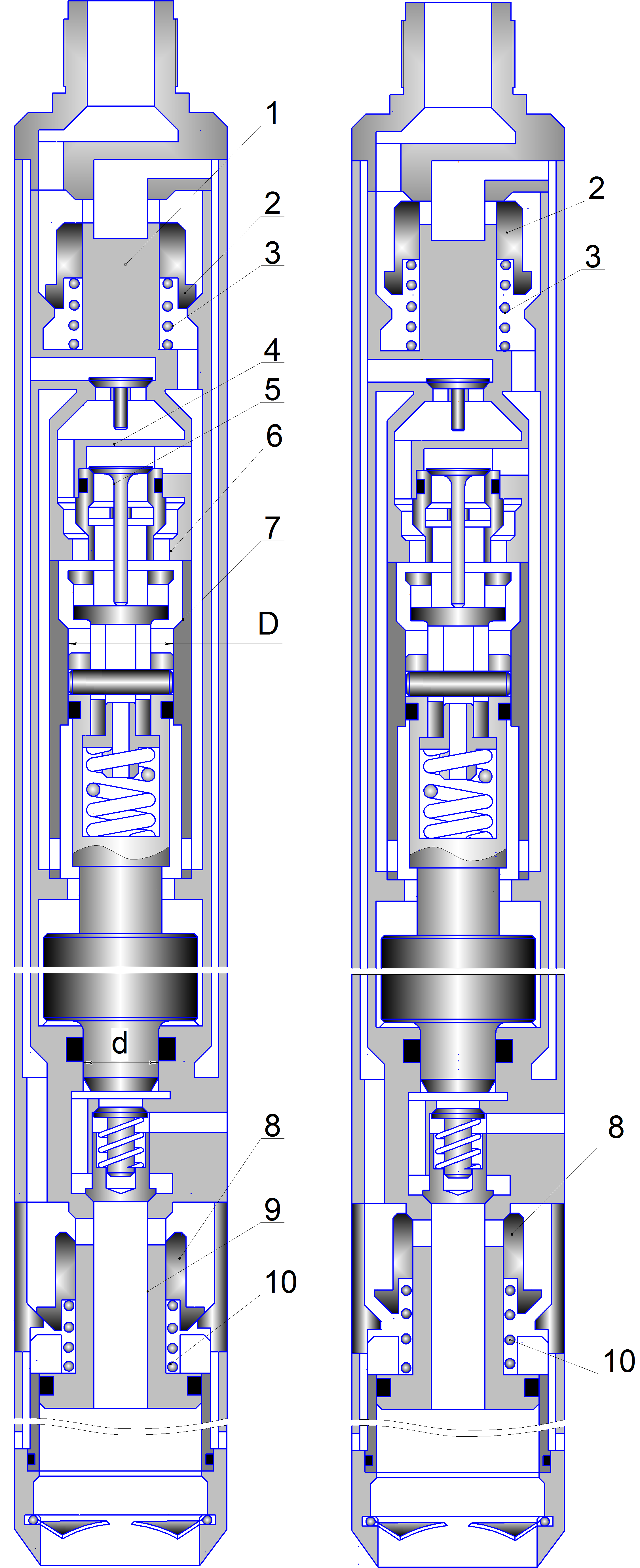
Shut-off system starting nodes GBS–127M standardized and implemented in the form of spring-loaded valves 2 and 8, concentrically mounted respectively on the rod 1 top launchers nodes and the stock 9 lower starting node[14].
Configuring nodes on the specified operating range of liquid flow provided by changing the precompression springs 3 and 10.
Availability of technological importance 140–200 l/min, significantly increased, above all, reliability retention elements unlocked with stop and control system hammers GBS–127M, which excluded the operation of lower starting node in the sampling period to ensure the preservation of the quality of the core during forced operation mechanism.
4. New technical solutions for improving plant UMB–130M
Questions remain problematic reliability launchers nodes GBS. First of all, technologically imperfect return operation is shut-regulatory systems starting nodes at the stage of hydraulic release mechanism. In approving the construction of launch sites GBS, the condition triggering lower starting node with gated access to the liquid core tube and the simultaneous change of the position of elements on the opening of the upper launcher assembly channels for admission flow chamber hammers implies the need to turn off the mud pump. This complicates management technology works, due to the presence of relatively long passive state of hydropercussion the drill in the well.
More complex work were associated with improvements in operational manageability launchers nodes. The concept of technical support increased levels of confidence starting nodes based on a preliminary study of the nature of changes in position and hold in a given state shut-regulatory systems starting nodes GBS–127M, are used in installations UMB–130M.
Given the resulting degree of operational manageability launchers nodes in shells GBS–127M, the basic idea direction adopted for further development, was to find solutions that provide increased strength return shut-regulatory systems upper and lower starting nodes, primarily on the operational phase of unlocking hammers.
Предложена принципиальная конструкция ЗРС, в виде концентрично размещенных, относительно друг друга, клапана 2 и плунжерного золотника 1[1].
Draft 4.1 – Schematic diagram of the starting node GBS–127M installation UMB-130M
Selecting a marked performance stop and control system adopted the assumption more force component to detach from the valve seat, due to its interaction with the shock ram spool, moving spring force.
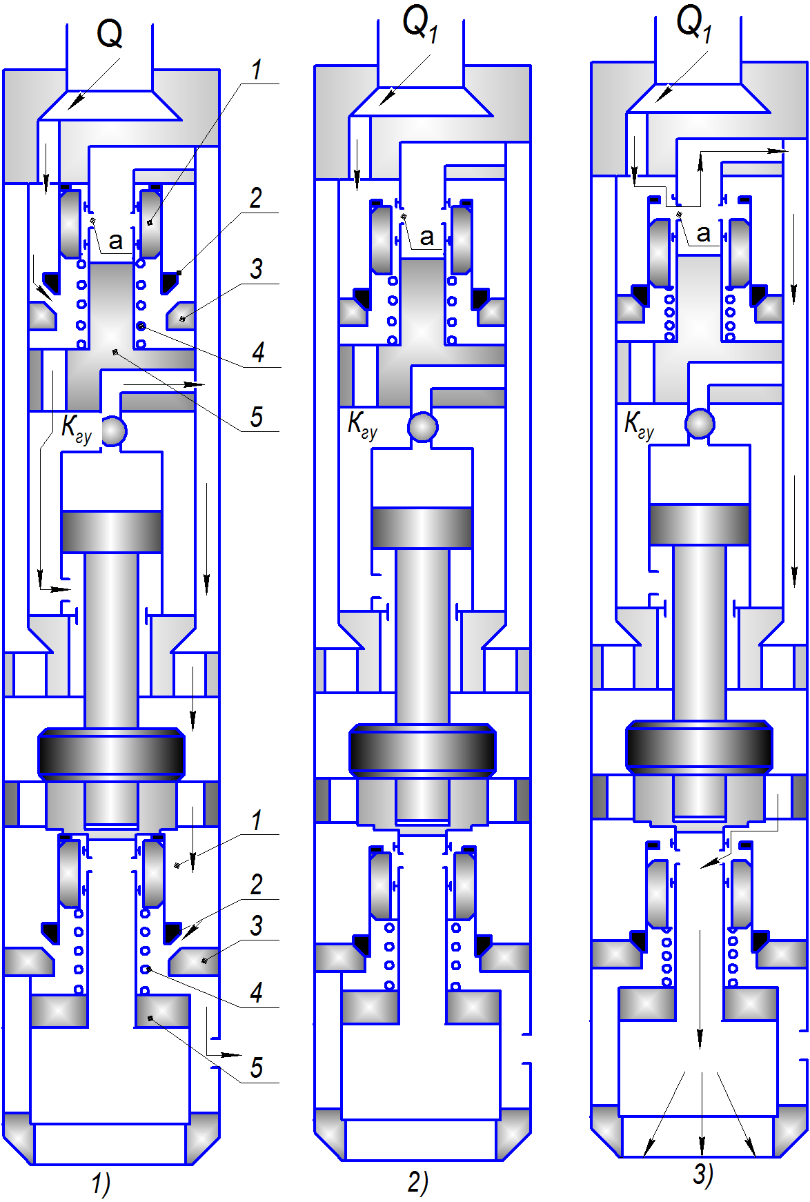
Starting position of the elements of nodes for coring is shown in draw. 4.1, 1. Plunger valve 1 and valve 2 as upper and lower starting nodes held the top position in the power of predeformed spring 4. Through the gap between the valve seat 2 and 3 in the working chamber hammers K
directed liquid flow corresponding to the nominal value of the pump to run and efficient operation.
To block the hammers on the implementation phase of the erosion of rocks, fluid flow in the hydraulic system increases to the design value, which leads to a shift of the valve-piston valve
before landing on the saddle valve 2 3 (draw. 4.1 ,2). In the future, there is an independent movement of plunger spools 1, with additional compression springs 4, to fully open the windows made in the relevant stocks 5 upper and lower starting nodes.
To return to the upper position stop and control system fluid flow is reduced, resulting in lower force on the plunger slide valves 1, 4 are respective springs move rapidly upward. In contact with the support arms 2 valves (draw. 4.1, 2), the latter, perceiving the cumulative effect of the spring 4 and the force of impact, together with the plunger 1 spool move to the position corresponding to the launch of hammers (draw 4.1, 1).
In this version, starting nodes opportunity to change the height of the slit valve independently of the process of opening windows. In a series of opening (closing) windows only involved a spring loaded plunger valve, an area in the design phase can be varied by changing the internal section of the valve. By reducing the working area of the valve it is possible to reduce the power incident on a liquid flow. Also, if you move up spool holds impact interaction and valve spool, which objectively can play a positive role in enhancing the reliability of condition stop and control system return to its original position[12].
Findings
Master's thesis is an actual problem, because Ukraine needs to perform large amounts of geotechnical studies, including-geotechnical drilling wells up to 50 meters, in order to reduce the economic costs of drilling carried out from boards not specialized ships and boats of various types with a sufficient energy supply, equipped with the respective mechanisms and having the possibility of staging the stern anchor, for the development of the Black and Azov Seas.
In carrying out the master's work developed a modified design of the hydraulic mechanism, selected new indicators and ratios hydropercussion machine, planned study parameters starting nodes and the conditions of their operational management, which will increase the effectiveness of multifunctional hydropercussion drill without columns for drilling wells up to 50 m from the board ships.
In writing this essay master's work is not yet complete. Final completion: October 2014. Full text of the work and materials on the topic can be obtained from the author or his manager after that date.
List of sources
- Калиниченко О.И., Хохуля А.В., Зыбинский П.В., Каракозов А.А. Установки для бесколонного бурения скважин на морских акваториях.–Донецк : Донбасс, 2013–158 с.
- 2. Асеев А.Г., Распопов В.М., Хворостовский С.С. Бурение разведочных скважин на шельфе.–М.: Недра, 1988.–197 с.
- 3. Башта Т.М. Объемные насосы и гидравлические двигатели гидросистем. М «Машиностроение», 1974.–606 с.
- 4. Владиславлев В.С., Хворостовский С.С., Истошин С.Ю. Пути развития техники и технологии бурения на шельфе. //Технология и техника геологоразведочных работ.–М.,–1980–Вып.4.–с. 24–35.
- 5. Калиниченко О.И. Основные зависимости для проектирования гидроударных буровых снарядов для однорейсового бурения подводных скважин //Сб. трудов VI международной научно-технической конференции «Машиностроение и техносфера на рубеже XXI века». Донецк, 2000, т.2.–С.10–13.
- Калиниченко О.И., Хохуля А.В. Задачи совершенствования технологических режимов многорейсового бурения скважин на морских акваториях //Сб. научн. трудов.–Вып.9.–Киев: ИСМ им. В.Н.Бакуля НАН Украины, 2006.–С. 47–50.
- Калиниченко О.И., Каракозов А.А., Зыбинский П.В. Погружная гидроударная установка УМБ-130 для многорейсового бурения подводных скважин //Сб. научн. трудов.–Вып.6.–Киев: ИСМ им. В.Н. Бакуля НАН Украины, 2003.–400 с.
- Калиниченко О.И., Хохуля А.В. Основные проблемы и пути совершенствования техники и технологи многорейсового бурения скважин на морских акваториях //Науковий вісник. №7, Національного гірничого університету. Науково технічний журнал. Дніпропетровськ, 2009. С. 45–50.
- Калиниченко О.И., Зыбинский П.В., Каракозов А.А. Гидроударные буровые снаряды и установки для бурения скважин на шельфе.- Донецк: «Вебер» (Донецкое отделение), 2007.–276 с.
- Калиниченко О.И., Каракозов А.А., Зыбинский П.В. Разработка погружных гидроударных снарядов для бурения подводных разведочных скважин со специализированных плавсредств //Сб. научн. трудов.–Вып.8.–Киев: ИСМ им. В.Н.Бакуля НАН Украины, 2005.–180 с.
- 11. Комаров Л.В., Курбатов А.К., Распопов В.М., Смолдырев А.Е. О технических средствах морского бурения «Изв. ВУЗов. Геол. и разведка», 1975, №11, с. 191–194.
- Неудачин Г.И., Коломоец А.В. Забойные гидроударные буровые механизмы //Совершенствование техники и технологии разведочного колонкового бурения. М.:Недра.1968. С.123–151.
- Калиниченко О.И., Хохуля А.В., Комарь П.Л., Тельбиш М.Ю., Мартыненко И.И. Новые возможности и продуктивность легких гидроударных установок для бурения инженерно-геологических скважин на морских акваториях //Сб. научн. трудов.–Вып.15.–Киев: ИСМ им. В.Н. Бакуля НАН Украины, 2012.–с. 100-125.http://www1.nas.gov.ua/
- Калиниченко О.И., Хохуля А.В., Парфенюк С.Н., Кошеверова Е.В. Повышение надежности бесколонного бурения скважин в условиях морских акваторий. //Сб. научн. трудов.–Вып.13.–Киев: ИСМ им. В.Н. Бакуля НАН Украины, 2010. С.96–99.
- Каракозов А.А., Калиниченко О.И., Зыбинский П.В., Хохуля А.В., Комарь П.Л., Гусев Е.А., Егоров Ю.П. Результаты опытной эксплуатации установки УМБ–130 при проведении геологосъемочных работ в Чукотском море.// Збірник наукових праць ДонДТУ. Серія гірничо-геологічна.–Донецьк (ДонДТУ), 2007.–Выпуск 6(125). С.53–57.http://info.donntu.ru/
- 16. Фальков И.М., Бабич В.А., Хамидуллин Р.Г., Лисагор О.И. Современное состояние техники и технологии морского инженерно-геологического бурения //Труды ВНИИморгео. Обзор.–Рига, 1986.–152 с.