
Содержание
- Introduction
- 1. GOAL AND TAKS OF THE RESEARCH
- 2.DEVELOPMENT AND IMPROVEMENT OF DISCHARGE SHAFT KILN
- 3. PHYSICAL MODELS OF DISCHARGE
- 4. PRACTICAL APPLICATION DEVELOPMENT RESULTS AND CONCLUSION
- Source List
Introduction
Lime is known not only as a building material, and of flux used in metallurgical processes for the removal of iron and steel of phosphorus. Lime obtained by firing limestone in special furnaces or rotary shaft type. Shaft furnaces currently performs rotor. With a variety of benefits itself shaft furnace operates in a stable regime in the case of unloading from it fire lime uniformly carried out with a given performance. These characteristics depend on the design and reliability of operation of the device allows the discharge of the material to the receiving hopper.
2. GOAL AND TAKS OF THE RESEARCH
Development of an approach to the unification of synthesis Moore FSM, directing on hardware amount reduction in FPGA is the goal of research.
Main tasks of the research:
- Analysis methods of minimization amount of states in completely and incompletely specified Moore FSM.
- Estimation ways of hardware amount reduction with the help of encoding states of Moore FSM.
- Search and detection characteristics of existing construction methods of logic circuits of Moore FSM and estimation possibilities of their use on FPGA.
- Association of functionally different optimization directions of Moore FSM hardware amount into the unified approach to synthesis and formation recommendations for it's use.
- Design of alternative variants of basic stages of unified Moore FSM synthesis process and estimate of it's efficiency.
2.DEVELOPMENT AND IMPROVEMENT OF DISCHARGE SHAFT KILN
Employees of the department MOZCHM Donetsk National Technical University, an apparatus for unloading shaft kiln equipped with a table, committing plane-parallel motion relative to its body. Apparatus (Fig.1) includes at 1 mounted with clearance relative to the shaft 2 on the rolling elements 3 placed in the recesses of supporting brackets 4 fixed uniformly on the perimeter of the inner cylindrical surface of the hopper 5 adjacent to the bottom of the shaft furnace and provided with a hinged door 6 . Above the central part of the hearth 1 in the gap between it and the lower end of the shaft 2 is placed a conical cap 7 rigidly connected with the housing of the furnace, to which 8 knives are attached with an adjustable angle of attack, are uniformly dispersed around the perimeter of the upper plane of the hearth 1. In the lower abutment surface a hearth formed two cylindrical openings in which are mounted for relative rotation of the fingers 9,10, each of which is rigidly fixed to the toothed wheels, respectively 11 and 12, mounted horizontally on vertical axles 13 and 14. Pins 9 and 10 are displaced in the same direction by the same distance from the vertical axis 13, 14 of gears 11, 12. Both of these wheels have the same dimensions and are synchronized with each other placed on one line of their centers of the driving gear 15 through the bevel gear 16 associated with the motor - reduction gear 17 fixed on the outer the surface of the hopper 5. Bearing Supports all the gears are placed on a support frame 18 mounted on the supporting stand 19..
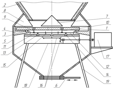
Figure 1 – Device for unloading of the shaft furnace, comprising a table with a plane-parallel motion.
The device operates as follows. After firing its lime pieces lie on the cover 7 of the top surface of the hearth 1, lying on its perimeter at an angle of repose and completely filling the gap between the hearth and the bottom of the shaft furnace 2. After opening the valve 6 and the switching motor - reduction gear 17, the rotation of its output shaft 16 through the bevel gear pinion 15 is transmitted, which results in a synchronous rotation of the gear wheels 11 and 12 on vertical shafts 13 and 14, bearing supports arranged in the support frame 18. However, the wheels 11 and 12 about the axes 13 and 14 will perform a rotational movement, vertical fingers 9 and 10 are located in cylindrical bores made in the lower support surface of the hearth 1. Due to the fact that the pins 9 and 10 are displaced by the same distance in one direction relative to the axis 13, 14 of gears 11, 12 rotating synchronously in the same direction, one will make a plane-parallel movement on the rolling elements 3 relative to the support arms 4 and the blades 8, as shown in FIG. 2, whereby the lime layer thickness equal to the gap between the bottom of the shaft 2 and the hearth 1, is nominated in a circle from the outlet opening of the annular shaft to the periphery of the hearth in the location area of knives 8 which are at a predetermined angle of attack will be reset in the material receiving hopper 5. According to the authors, the proposed device for unloading silo lime-gas furnace will increase the uniformity of the material issue, as it will be unloaded in a continuous mode with simultaneous discharge of all the blades around the perimeter of the movable hearth. Device for unloading of a shaft furnace equipped with mobile scrapers.
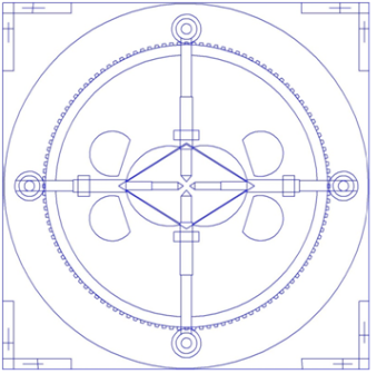
Figure 1.1 – Device for unloading of a shaft furnace equipped with mobile scrapers.
This discharge system from the shaft lime kiln comprises a square supporting platform 1 with 4 supporting column 2 and the central circular opening, which adjoins the bottom hopper 3. K platform with a gap by the spacers 4 and the clamping screw 5 is attached from above the supporting chuck in hole 4 which is fixed jumpers round at 7, with the edge of the hole forming arcuate slits 8. Faceplate about its jumper holes along two mutually perpendicular diameters of pairwise rigidly anchored horizontally disposed guides in the form of hollow cylinders 9, each of which is mounted for movement relative to the slide ends of the sliders are provided with 10.Perednie cores from 11 oriented towards the center of the hearth 7, and two horizontal lugs 12. Blizhnie lugs adjacent sliders interconnected hinged scrapers 13 in the form of petals. The second end of each slide by a connecting rod 1 is connected with a crank 15 rigidly fixed on the top of the vertical shank spur gear shaft 16, bearing assemblies are housed in housings platform 1 and the chuck 6. All four of the pinion shaft 16, driven in rotation by a motor - reduction gear 17 are meshed with a ring gear, a synchronizer 18, concentrically disposed in the gap between the body 1 and the face plate 6 and 8 centered .yu vertical rollers 19, mounted in a freely 20. Kazhdaya rotation axes of the two pairs of crank mechanisms located on opposite ends of the same diameter, operating in antiphase. Option (2) The material is unloaded with the help of two pairs of scrapers moving along the surface of the table with the help of structured mutually interconnected crank mechanism, an electromechanical drive and ring gear. For pre-verify that Offers systems and choice of rational decisions had been made physical models of their photos.
3. PHYSICAL MODELS OF DISCHARGE .
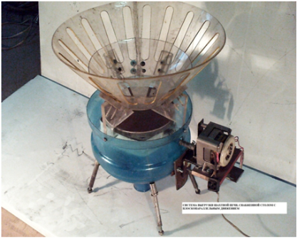
Figure 2 – MODEL unloading system with movable table.
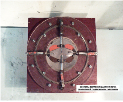
Figure 2.1 – MODEL Delayed MOVING scrape.
The results of the preliminary set of indicators for rational should adopt a system with movable table which was used in further studies. During the laboratory exercise of this power settings and the uniformity of the furnace to control the torque system is also investigated.
3.PRACTICAL APPLICATION DEVELOPMENT RESULTS
1.The results of these studies formed the basis for recommendations on calculation and design of systems of unloading mine kiln as part of the Department for MOZCHM research "Select the type of calculation and design of the drive unloading table for shaft kiln lime" under a contract №14-187 between the Donetsk National Technical University and the NPP in the form of "news" with funding of 20 thousand. UAH.
2.Experimental data prepared for publication in the international scientific and industrial magazine "Metallurgical processes and equipment." 3.Research materials used in the preparation of guidelines for laboratory work on the course "Physical modeling of technical systems" (for students of the specialty 8.05050311 "Metallurgical Equipment").
4.Zayavlenie the alleged invention.
This master's work is not completed yet. Final completion: December 2015. The full text of the work and materials on the topic can be obtained from the author or his head after this date.
Source List
1.Monastyrev AV Alexandrov AV Ovens for the production of izvesti.Spravochnik. - M .: Metallurgy, 1979. - 232 with.
2.Tabunschikov NP Production of lime. - M .: Chemistry, 1974. - 240 p.
3.Monastyrev AV Production of lime. - M .: Higher School, 1978. - 225 p.
4.Proizvodstvo lime and carbonation gas in the sugar mills / NP Herdsmen, ET Aksenov, RJ Gurevich, LD Shevtsov. - M .: Light and food industries, 1981. - 176 p.
5.Barenboym AM, Galiev TM, Ginsburg DB et al. - M .: Story-izdat, 1964.
6.Levchenko PV Calculations furnaces and dried silicate promyshlennosti.- M .: Higher School, 2007. - 368 with.
7.Nikiforova NM Heat machinery and thermo-equip enterprises of the industry of building materials and products. - M .: Higher School, 1981. - 270 p.
8.Ogneupory and refractory products. - M .: Publishing House of Standards, 1975. - 671 with.
9.Vorobev HS, DY Mazurov Teplotehnologicheskih processes and devices of silicate industry. - M .: Higher School, 1965. - 773 p. 10.Spravochnik for designing cement plants / ed. SI Danyushevskogo. L .: Stroyizdat, 1969. - 240 p.