Contents
- Introduction
- 1. The main elements of hydraulic equipment
- 2. Vibration linearization dry friction force decoupler
- 2.1 The physical nature
- 2.2 Reduced friction in the slide valve
- 2.3 Vibration linearization in electrohydraulic distributors
- Conclusion
- List of sources
Introduction
Known advantages of hydraulic and pneumatic components and systems led to their widespread use in virtually all fields of industry. Basic and integral part of the hydraulic system is a hydraulic system, the characteristics of which, to a large extent, determine their technical level, efficiency and reliability.
1. The main elements of hydraulic equipment
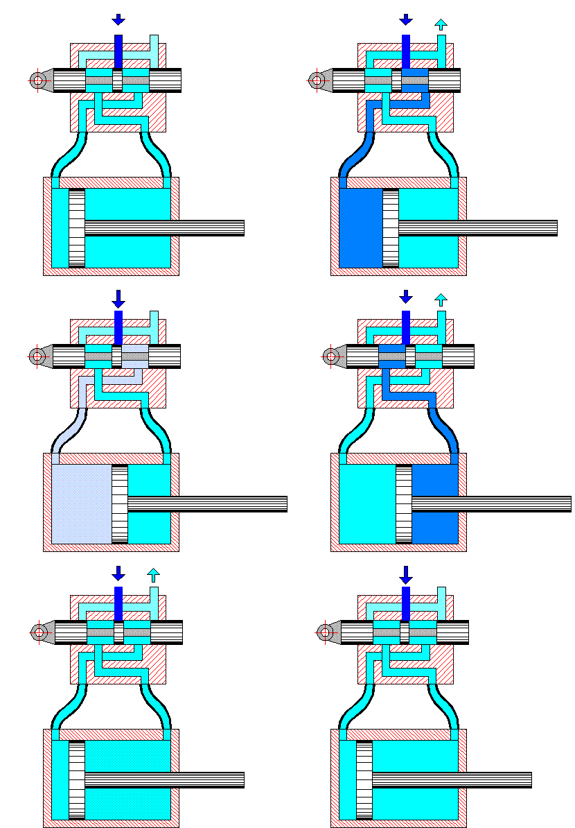
The main structural element is a hydraulic equipment locking and control element. Of the variety of hydraulic equipment most widely hydroapparatuses with shut-off and regulating element in the form of a pair of precision-plunger sleeve (spool valves) [6]. They are used at nominal pressures up to 32 MPa. With the slide valve, as well as by other types of valves, manages the direction of the working bodies of hydraulic motors (hydraulic shafts and piston rods of hydraulic cylinders). The principle of slide valve shown in Fig. 1.

Figure 1 – The operating principle of slide valve
(animation: 11 frames, 5 cycles of repetition, 57 kilobytes)
2. Vibration linearization dry friction force decoupler
2.1 The physical nature
The physical essence of vibrational linearization. The hydraulic vibration apparatus linearization (implementation of additional vibration shutoff element, a relatively high rate, with the help of an external periodic force) is used to eliminate from consideration of dry friction force FTP, which is approximately constant in magnitude and changes its sign when the sign of the speed of relative movement VZRE rubbing parts (ZRE speed), as shown in Fig. 2, a [1 – 3].

Figure 2 – Vibration linearization dry friction force decoupler
2.2 Reduced friction in the slide valve
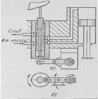
To reduce friction and high accuracy plungers copying spool longitudinal reported (Figure 3, a) and turning (Figure 3, b) oscillatory (oscillatory) motion. Figure 3, a shows a circuit construction in which the eccentric sleeve spool reported axial movement. The amplitude of the axial vibration of the sleeve is usually chosen from 0.1-0.2 to 0.01-0.03 mm, and the frequency of 25-50 Hz to 100 Hz. The rotational vibrations of the plunger valve (Fig. 3, b) are carried out with an amplitude of about 4? and switching frequency of 50 vol./c. [7].

Figure 3 – Spool device with longitudinal and rotary oscillating motion
2.3 Vibration linearization in electrohydraulic distributors
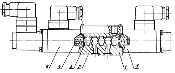
The electrohydraulic distributors of RP6 Pavlovsky machine-building factory Voshod
vibrating linearization is carried out by the introduction of electromechanical converter auxiliary winding, which is fed a signal with a frequency of 300 Hz. This has enabled to suppress the magnetic hysteresis of the electromechanical transducer formed of a relatively inexpensive magnetic material substantially eliminate friction in the movable members and reduce the influence of the positive overlap of the spool to the precision drive parameters [4, 5].

Figure 4 – Distributor type RP6
Conclusion
In summary we can conclude that: a stable trend to improve the dynamic characteristics of hydraulic equipment is manufactured vibrational linearization method of implementation, which is most advantageously carried out by means of hydraulic vibratory circuits with frequency from 50 to 300 Hz, with a small (0.1-0.5 mm) positive spool overlap.
In the future master's work is aimed at obtaining a mathematical model of the work of the spool of the distributor and the establishment of specific relationships between its parameters.
In writing this essay master's work is not yet complete. Final completion: December 2015. Full text and materials on the topic can be obtained from the author or his manager after that date.
List of sources
- Андренко П. Н. Вибрационная линеаризация – эффективный путь улучшения динамических характеристик гидроаппаратов / П. Н. Андренко // Вибрация в технике и технологиях. – Винница, 2003. – № 2 (28). – [С. 39-45].
- Тарко Л. М. Волновые процессы в трубопроводах гидромеханизмов / Л. М. Тарко. – М.: Машгиз, 1963. – 183 с.
- Андренко П. Н., Дмитриенко О. В., Асатрян Р. Я. Использование пульсаций рабочей жидкости в системах гидроприводов / П. Н. Андренко, О. В. Дмитриенко, Р. Я. Асатрян // Вестник ХГПУ “Механика, машиностроение”. – Харьков: ХГПУ, 1997. – Вып. 7, Ч. 2. – [С. 35-37].
- Андренко П. Н., Дмитриенко О. В., Белоусов Э. В. Экспрериментальное исследование преобразователей пульсаций / П. Н. Андренко, О. В. Дмитриенко, Э. В. Белоусов // Вестник ХГПУ “Новые решения в современных технологиях”. – Харьков: ХГПУ, 2000. – Вып. 79. – [С. 32-33].
- Андренко П. М., Дмитрієнко О. В. Математичні моделі і розрахункові дослідження гідравлічних гасителів і підсилювачів пульсацій тиску / П. Н. Андренко, О. В. Дмитрієнко // Східно-Європейський журнал передових технологій. – 2004. – № 5 (11). – [С. 88-93].
- Андренко П. Н. Выбор параметров осцилляции запорно-регулирующего элемента гидроаппарата с гидравлическим вибрационным контуром / П. Н. Андренко// Вісник Сумського державного університету. – Суми: СумДУ, 2003. – № 13 (59). – [С. 31-38].
- Меднис В. Выбор параметров осцилляции золотника пропорциональных гидравлических аппаратов / В. Меднис // Вестник Национального технического университета
Харьковский политехнический институт
. – Харьков: НТУХПІ
, 2001. – Вып. 129 Ч. 1. – [С. 120-124].
