
Abstract
Сonten
- Introduction
- 1. Relevance of the topic
- 2. The purpose and objectives of the study
- 3. The current state of research question
- Conclusions
- Source list
Introduction
Gear coupling is a rigid compensating coupling, which consists of a half-coupling with external gear teeth, and a detachable holder with two internal toothed crowns (fig.1).
Figure 1 – Animated detailing CG (frames – 8, quantity of cycles of repetition – 10, volume – 199 KB)
These devices are designed to transmit torque between two shafts whose axes are not collinear. In other words, the gear coupling compensates for axial, radial and angular shaft misalignment (fig. 2). This is achieved due to the fact that its gearing is manufactured with a guaranteed side clearance and with the possibility of a free axial displacement of the conjugate teeth, and the teeth themselves are barreling shape with a spherical outer surface. Compensation shaft alignment deviations accompanied slippage teeth[1 – 2].
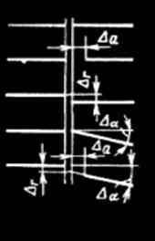
Figure 2 – Types of deviations
The ability to compensate for angular displacement (Δα) in gear couplings tend to be limited to the value of 4-5°. There is a type of gear couplings, designed to connect two nominally coaxial shafts. Such couplings can compensate for small deviations in the axial alignment (Δr), such as errors in setting shaft displacement during operation. Such couplings compensate for angular ability is limited to 0,25…0,5°. Compensating ability gear couplings at linear displacemen (Δа) and 4 mm.
In practice, most often found combination of these variations, called "shaft misalignment."
Compensation for the harmful effects of misalignment of shafts is achieved: a result of mobility is almost hard parts - in rigid compensating coupling; by elastic deformation of parts - in the flexible coupling [3 – 4].
Load and compensating abilities gear couplings depend on several factors, including the type of geometry of the lateral surface of the teeth of the sleeves and the stiffness of parts and their individual elements.
Initially, the teeth of the toothed couplings bushings performed were performed with straight involute teeth. These gear couplings compensate for small shaft misalignment angles (30'), due to the occurrence of the edge contact of teeth that greatly worsened working conditions of the clutch and reduced its share. Later, to increase the ability of compensating couplings reduces the length of the sleeve teeth and rounded their edges. In such gear couplings at high angles of the axes of the shafts skew number of loaded tooth was limited to two diametrically opposed and then there was a need for alignment of the coupling halves. Further development of the design of toothed couplings led to the fact that the outer surface of the teeth of the sleeve began to make a sphere with center on the axis of symmetry of the ring gear bushing. The teeth of the sleeve in this case also have a rectilinear manner as in the first type of coupling, and as a consequence the same drawbacks. [5].
1. Relevance of the topic
Currently to enhance load and compensating abilities toothed couplings used longitudinal and profile modification of teeth [6 – 8]. Longitudinal modification of the teeth is used to compensate for axial installation errors couplings. Thus forming the side surface of the teeth of the sleeve may be broken – bilateral oblique, elliptical, circular, etc. that are determined applicable to the coupling requirements. However deflection curves from each other within the width of the sleeve slightly, so the most technologically to manufacture is to approximate original contour line offset circumferentially. Offset angle coupling does not exceed 45' and has the following disadvantages: the contact of the teeth in some cases is a point, and this negatively affects the durability of the coupling, the contact patch moves to the top of the tooth of the sleeve because of the angle of contact between the involute profiles, due to the tangential displacement of the working surfaces of the teeth of the load on the perimeter of the gear couplings are distributed unevenly.
Profile modification of teeth is used to compensate for radial installation errors couplings[9 – 10]. The introduction of the profile modification of the teeth of the coupling eliminates the concentration of contact stresses along the height of the teeth. That is, the profile modification of the teeth of the partly solves the problem of contacting the tops of the teeth of the sleeve and collars as well with a limited angle of misalignment of the teeth.
Further development of the shape of the tooth bushing has led to a realization on its side surface, spatial geometry, or a geometry that corresponds to their natural wear and tear during operation [11 – 13]. However, the known spatial geometry ensures linear contact and uniform distribution of load between the teeth of the sleeve and clips work well in conditions for which they were designed and manufactured.
Together with the creation of new geometries of the lateral surface of teeth sleeve developed and improved technological methods of production. So ways to get teeth straight generatrix similar methods for producing the teeth of cylindrical gears. Ways to get teeth with longitudinal modification are mainly based on the methods of obtaining the teeth with rectilinear generatrix and are usually manufactured on the same equipment. Obtaining longitudinal modification is the introduction of additional oscillatory or rocking motions of the workpiece or moving the axis of the blank on a special path in the space implemented with the use of the copier.
On the basis of the conducted analysis of the existing geometries of the teeth of the toothed sleeve and technological methods for their preparation, to expand the operational capabilities of toothed couplings, relevant is the creation of a new spatial geometry of the teeth, which would allow to maintain linear contact and a uniform load distribution between the teeth in the mix in some interval of values of angles of misalignment of teeth due to the choice of the rational element stiffness gear couplings.
2. The purpose and objectives of the study
Object of research – the elements of design of the gear sleeve and the technological process of its manufacture.
The aim of the study is to develop a design and process to ensure a uniform distribution of the load in the connection between the teeth of the sleeve and the clips and raising the carrier and the compensating ability of toothed couplings by changing the stiffness of the hub sleeve.
The main objectives of the study:
- Perform analysis of existing structural elements of toothed couplings, contributing to the equalization of the load on the connection, the operating conditions of toothed couplings and technological methods of education in the form of gear rims sleeve and clips.
- To investigate the stress-strain state of the sleeve gear couplings when there is error in the mounting of the shafts.
- Develop design to ensure a uniform distribution of the load in the connection between the teeth of the sleeve and the clips and raising the carrier and the compensating ability of gear couplings.
- To develop a technological method of manufacturing the sleeve gear couplings with reduced stiffness of the hub sleeve.
- To develop the tooling for the manufacture of toothed couplings bushings with reduced stiffness of the hub sleeve.
3. The current state of research question
It is known that increasing the durability of the machines even slightly leads to a large saving of metal, reducing the cost of production of the spare parts, the reduction of the number of repairs, and therefore, the increase of actual working machines. Design methods to improve the durability based on the choice of materials and the combination of the hardness of parts in friction pairs, replacing in machine parts sliding friction by rolling friction, and their combination, the change of stiffness, pliability associated components, etc.
Design methods to improve the durability based on the refinement of the calculation of forces and stresses [19 – 21], operating parts, and the use of parts and components with greater efficiency.
When you increase the radial clearance of the hub axle and clips are installed, compensating for manufacturing errors and Assembly, diametrically spaced teeth evenly come into work and the number of pairs of teeth that transmit the load increases. The experiments compare the load capacity of the couplings [22 – 23] with alignment without alignment showed an increase in the efficiency by about 20 ... 25%.
Significant influence on the uniformity of load distribution between the teeth has a design rim bushings and increases the pliability of the teeth. The clutch teeth have a certain flexibility. When the load of the first pair or the first pair of teeth are deformed, which leads to the redistribution of gaps between all the teeth (gaps decrease). If the deformation of the first pair of teeth is greater than or equal to the gap in the second pair, it comes in contact. With a further increase of the load increasing the number of teeth in contact and work. Last pair, came into contact, will be one in which the gap is equal to or less deformation of the pair of teeth of the first coming into operation. The increase in the number of pairs of teeth during application of the load occurs symmetrically with respect to the pair who had come in contact, since the gaps are also symmetrically distributed about the axis of the largest distortions. The mutual angle of contact of the teeth of the sleeve and the cartridge is changed with the change of the angle position of the tooth. With the change of the mutual contact angle changes the stiffness of the tooth. Within the contact zone, the contact area is moved between the end and the middle tooth of the sleeve. Therefore, when passing a couple of teeth through the contact area of its rigidity varies continuously. Thus, in a given time in the transmission of power involved teeth with different stiffness.
Tooth movement consists of private movements of bending δи, contact compression δк and displacement δо due to the elastic deformation adjacent to the tooth portion of the rim::
δ=δи+δк+δо.
Thus, while controlling for the optimum design of the rim of the ring gear sleeve, you can change the displacement δо, of that will make the tooth more pliable, and thus to increase the number of pairs of teeth involved in the coupling [24 – 28]. Gear couplings GOST 2742-94 have a gear sleeve in the form of a disk with the hub. In this case, the rigidity of the teeth, working the outer and inner ends of the same. Forces acting on the teeth which contact the outer and inner ends, different. So, to equalize the load between the ends you can set the desired direction of deformation of the rim. To check this situation was a comparative experiment to determine the number of teeth that transmit the load to toothed couplings with different configuration and compliance of the rim of the sleeve. The experiment was conducted on models with optically active material. Tested eight designs clips bushings (fig. 3). The benchmark for comparison made solid gear ring. Considered models with number of teeth Z = 40 and m = 3 mm.
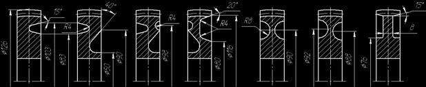
Figure 3 – Design models gear sleeves
To reduce the influence of the inaccuracy of manufacturing the experiment was conducted on two models of bushings with the change of the structure of the rim of the bushing on a lathe. Load models was carried out with the skew angle of the axes of the bushings and clips ω=30' and the same load. In polarized light counted the number of teeth that transmit the load.
It is established that the contact patch more evenly in a symmetric structure due to the different flexibility of the ends, the load distribution between diametrically opposite teeth different [29 – 33].
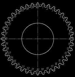
Figure 4 – The numbering of the teeth models
In addition to increasing size of the undercut of the rim of the sleeve, the number of teeth that transmit the load increases.
As a result of the experiment set of the contact zone for different designs of toothed couplings bushings but have not installed real values of the stresses in the teeth.
The analytical solution to this problem is quite difficult, as the processes have not been studied. The most efficient for the solution of this problem is the method of numerical analysis [34 – 36], which allows to determine the value of many process parameters (strain, stress), but also to determine the dynamics of the process. Numerical analysis was conducted by finite element method using the ANSYS program. To facilitate the calculations of the solid model of the gear coupling has been significantly simplified. In particular, from the entire volume of the clutch was left only the part that is adjacent to the toothed crown, also with 36 teeth gear was left only 18 (9 diametrically opposite). For the study made three designs sleeve (fig. 5).
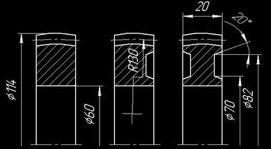
Figure 5 – Sleeve design for numerical analysis by finite element method
When solving the tasks for the simulation of real conditions of operation of the coupling gear sleeve is rotated on the vertical axis by 1°. The clip is attached, and to the teeth of the sleeve the load is applied. In the process of solving the problem using ANSYS package for each design of the sleeve was obtained finite element model of the gear sleeve (fig. 6).
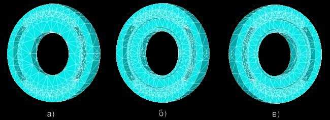
Figure 6 – Finite element model of gear couplings: a – bushing with a solid end face; b – bushing with symmetrical ends; c – sleeve with asymmetrical ends
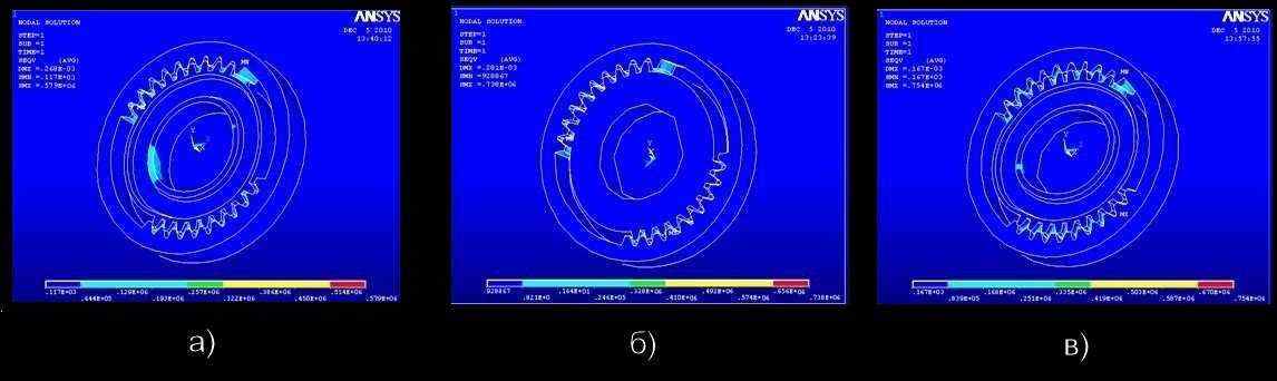
Figure 7 – The stress distribution between the teeth of the clutch: a – bushing with a solid end face; b – bushing with symmetrical ends; c – sleeve with asymmetrical ends
As a result of the calculation obtained the following picture of the stress distribution between the teeth of the sleeve gear couplings (fig. 7). The maximum stresses occur in the contact areas of the teeth of the sleeve with the ends which are asymmetrical – 754 MPa (fig. 7, c), the lowest – 579 MPa characteristic bushings with symmetrical ends(fig. 7, b), in the sleeve with solid ends of the maximum stress in the contact zone of the teeth is 738 MPa.
A more favourable distribution of load between the teeth of the coupling can be achieved by reducing the width of the tooth of the sleeve and increase the distance between the toothed crowns of the bushings [38 – 41]. However, it is necessary to consider other factors limiting the size of the named parameters. In particular, the increase of the distance between the toothed crowns of the bushings increases the size of the coupling, while increasing its compensating ability.
At relatively low sliding speeds in the friction zone, as well as violations of lubricating mode that could be caused by ingress of abrasive material in the lubricant and breaks his submission, it may be setting the I kind. Therefore, an important design challenge is to create a working seal that protects the friction from the abrasive, securely hold the lubricant in the cavity of the coupling, and promote within a predetermined range of sliding speeds and normal loads of friction.
Conclusions
Based on the analysis of works devoted to the issue of increasing the wear resistance and durability of gear couplings, as well as on the basis of the conducted research, the following suggestions and recommendations that will help to significantly increase the life of gear couplings.
At the design stage should:
- To increase the elasticity of the clips and the sleeve gear couplings. The elasticity of the clips to increase by reducing its thickness, the elasticity of the sleeve be increased by changing the design of the hub.
- To reduce the width of the tooth of the sleeve and to increase the distance between the toothed crowns of the clips. But it is necessary to consider that the increase of the distance between the sleeves leads to increase the dimensions of the entire coupling, while increasing its compensating ability.
- Even at small angles of tilt shafts combine to give preference to toothed couplings with modified tooth sleeve, which eliminates the occurrence of edge contact.
- To use a more wear-resistant materials. For example, when abrasive wear is perhaps the use of normalized steel 65G, containing 0,9–1,2% of manganese. He increases the strength and hardness of steel, while reducing its viscosity.
- Increasing the diameter of the screws for fastening covers seals, which would entail changing the design of the cover itself.
At the manufacturing stage:
- Assign final processing that meets the conditions of operation of gear couplings. If the coupling is operated under such conditions that contribute to the setting of the First kind, oxidation or abrasion, when the final processing is necessary to increase the hardness of the surface layer. For this we need to use thermal or chemical-thermal processing.It is best to use plastic-surface processing that may be performed by various methods, but for gear bushings and clips of the most rational is shot peening. If tooth clutch operates in conditions of occurrence of fretting, it is necessary to increase the corrosion resistance of the working surfaces through the use of the chrome coating of the teeth.
- Need to apply thermal or chemical-thermal processing. It can be surface hardened teeth with high-frequency current (HFC), laser hardening or heating in the electrolyte. The core parts remain the same as during quenching, and the outer layer becomes hardness up to 65 HRC. The use of ion nitriding can improve the wear resistance of the teeth in 3-4 times in comparison with hardened annealing (HFC).
At the stage of operation to comply with the following recommendations:
- To appoint a lubricant on physical and chemical properties conforms to the conditions of operation of the coupling. Gear couplings work in conditions of boundary friction, so when high loads need to use solid lubricants are graphite, molybdenum disulfide. For smaller loads good extreme pressure properties are additive with the sulfur to be used at temperatures of about 200°C. If the temperature in the friction zone of the teeth does not exceed 150°C, it is possible to use chlorine additives. At temperatures above 200°C as an additive to applied phosphorus. Also important is the timely replacement or cleaning oil.
Source list
- Uran. Зубчатая муфта [Электронный ресурс]. – Режим доступа: http://www.uran.donetsk.ua/~masters....
- Reductorntc-k. Муфта зубчатая [Электронный ресурс]. – Режим доступа: http://www.reduktorntc-k.com.ua/produkt....
- Айрапетов Э. Л. Зубчатые соединительные муфты / Э. Л. Айрапетов, Д. Б. Миржаджанов. – М.: Наука, 1991. – 250 с.
- Калашников С.Н. Производство зубчатых колес: Справочник / С.Н. Калашников, А.С. Калашников, Г.И. Коган и др.; Под общ.ред. Б.А. Тайца. – 3-е изд., перераб. и допол. – М.: Машиностроение, 1990. – 464 с.
- Мокид Зубчатые муфты. Исследование и оптимизация // Труды Амер. об-ва инженеров механиков. Сер. В. Конструирование и технология машиностроения. – 1968. – №3. – С. 1–10.
- Тернюк Н.Э. Метод синтеза модификаций зубьев цилиндрических колёс / Б.С. Котляров, А.В. Павленко // Теория реальных передач зацеплением. – Курган, 1988. – С. 120–121.
- Уткин Б.С. Оптимизация геометрических параметров зубьев зубчатых муфт / Б.С. Уткин, А.И. Роббер // Вестник машиностроения. – 1985. - № 8. – С. 32–33.
- Плахтин В.Д. Синтез зацепления зубчатых муфт с повышенными углами перекоса соединяемых валов / В.Д. Плахтин, М.Ю. Ивочкин // Вестник машиностроения. – 2003. – №6. – С. 3–9.
- Коськин В.Н. К вопросу о выборе рациональной формы зубьев зубчатых муфт // Изв. вузов. Машиностроение. – 1973. – № 4. – С. 53–57.
- Елисеев Ю.С. Деформации и погрешности в зацеплении и их роль в работе зубчатой передачи / Ю.С. Елисеев, И.П. Нежурин // Вестник машиностроения. – 1999. – № 8. – С. 28–31.
- Михайлов А.Н. Геометрический и кинематический анализ зацепления прямозубых цилиндрических колес при наличии монтажных погрешностей / А.Н. Михайлов, Г.В. Горецкий // Прогрессивные технологии и системы машиностроения: Межд. сб. научных трудов. – Донецк: ДонГТУ, 2002. – Вып. 19. – С.145–150.
- Зак П.С. Перекосы тяжелонагруженных зубчатых передач и продольная модификация зубьев / П.С. Зак, А.Е. Уздин // Вестник машиностроения. – 1988. – №2. – С. 12–14.
- Шевелева Г.И. Алгоритм геометро-кинематического анализа зацепления зубчатых колес / Г.И. Шевелева, А.Э. Волков, Медведев В.И. // Вестник машиностроения. – 2004. – № 8. – С.3–9.
- Лукичёв А.В. Исследование долговечности зубчатых муфт при тяжёлых эксплуатационных условиях // Научные достижения и опыт отраслей Машиностроения - народному хозяйству: Республиканская н/т конференция. – Севастополь, Харьков: ВНТОМ. – 1991. – С. 36.
- Польченко В.В. Износ в зубчатых муфтах / В.В. Польченко, А.Н. Михайлов // Прогрессивные технологии и системы машиностроения: Межд. сб. научных трудов. - Донецк: ДонГТУ. – 1997. – Вып. 4. – С. 131–135.
- Польченко В.В. Определение долговечности зубчатых муфт с учётом износа и распределения нагрузки между зубьями / В.В. Польченко, М.А. Сурело // Прогрессивные технологии и системы машиностроения: Сборник научных трудов. - Донецк: ДонГТУ. – 2000. – Вып. 10. – С. 210–213.
- Польченко В.В. Влияние эксплуатационных параметров на износ в зубчатых муфтах / В.В. Польченко, С.С. Москин // Прогрессивные технологии и системы машиностроения: Межд. сб. научных трудов. – Донецк: ДонГТУ. – 1999. – Вып. 7. – С. 155–165.
- Польченко В.В. Долговечность зубчатых муфт / В.В. Польченко, В.А. Богуславский // Прогрессивные технологии и системы машиностроения: Межд. сб. научных трудов. – Донецк: ДонГТУ. – 2002. – Вып. 23. – С. 110–116.
- Онищенко В.П. Прогнозирование формы профилей зубьев зубчатых передач в результате их износа // Прогрессивные технологии и системы машиностроения: Межд. сб. научных трудов. – Донецк: ДонГТУ. – 1998. – Вып. 5. – С. 155–163.
- Заблонский К.И. Зубчатые передачи. Распределение нагрузки в зацеплении. – Киев: Техника, 1977. – 208 с.
- Устиненко В.Л. Напряженное состояние цилиндрических прямозубых колес. – М.: Машиностроение, 1972. – 92с.
- Кудрявцев В.Н. О методах оценки несущей способности цилиндрических зубчатых передач / В.Н. Кудрявцев, Д.Н. Решетов, И.С. Кузьмин, А.Л. Филиппенков // Вестник машиностроения. – 1989. – №10. – С. 16–21.
- Буланов Э.А. Сравнительная оценка прочности зубьев зубчатых колес / Э.А. Буланов, A.A. Зубарев // Техника машиностроения. – 2005. – №1. – С. 12–17.
- Айрапетов Э.Л. Совершенствование методов расчета на прочностьзубчатых передач // Вестник машиностроения. – 1993. – №7. – С.5–14.
- Семенча П.В. Распределение напряжений по длине бочкообразных зубьев / П.В. Семенча, Ю.А. Зислин, Н.Б. Шубина // Вестник машиностроения. – 1970. – № 12. – С. 22–23.
- Айрапетов Э.Л. Роль кромочного контакта в обеспечении контактной прочности зубчатых колес / Э.Л. Айрапетов, Э.Д. Браун, Н.В. Чичинадзе, И.А. Копф, В.В. Корнилов // МиТОМ. – 2002. – №9. – с. 36–38.
- Попов А.П. Контактная прочность эвольвентного зацепления с учетом перекоса зубчатых колес / А.П. Попов, А.С. Каиров // Прогресивні технології і системи машинобудування: Міжнародний зб. наукових праць. – Донецьк: ДонНТУ. – 2007. – Вип. 34.– С. 183–189
- Айрапетов Э.Л. Определение контактной деформации зубьев цилиндрических зубчатых колес // Вестник машиностроения. – 1967. – №1. – С.32-35.
- Айрапетов Э.Л. Расчет контактных напряжений в передачах зацеплением с локализованным контактом зубьев / Э.Л. Айрапетов, С.Э. Айрапетов, Т.Н. Мельникова // Вестник машиностроения. – 1985. – №12. – С. 6–8.
- Уткин В.С. Определение надежности зуба прямозубой зубчатой передачи по условию контактной усталости // Вестник машиностроения. – 2007. – №3. – С. 25–28.
- Михайлов А.Н. Методикарасчета распределения нагрузки по пятну контакта зуба зубчатой муфты, при перекосе осей валов / А.Н. Михайлов, Р.М. Грубка, С.А. Рыбина, Е.А. Буленков // Прогрессивные технологии и системы машиностроения: Межд. сб. научных трудов. – Донецк, 2002. – Вып. 19. – С. 151–157.
- Ристивоевич М. Влияние длины контактных линий на контактные напряжения зубьев цилиндрических зубчатых передач / М. Ристивоевич, Т. Лазович, Р. Митрович, М. Ристивоевич, Р. Митрович, Т. Лазович // Техника машиностроения. – 2001. – № 2. – С. 34–38.
- Айрапетов Э.Л. Влияние изгибной деформации зубьев; прямозубых цилиндрических передач на параметры контакта зубьев / Э.Л. Айрапетов, Ф.Г. Нахатакян // Вестник машиностроения. – 1990. – №8. – С. 21–23.
- Кириченко А.Ф. Теория, расчет и анализ объемного напряженно- деформированного состояния зубьев цилиндрических колес при изгибе: Автореф. дис. доктора техн. наук / ХПИ. – Харьков, 1991. – 498с.
- Айрапетов Э.Л. Экспериментальное исследование статической нагруженности зубчатых муфт / Э.Л. Айрапетов, В.И. Ковалевский, К.А. Мартиросов // Вопросы повышения работоспособности машин. – Ташкент, 1979. – Вып. 266. – С. 40–45.
- Польченко В.В. Распределение нагрузки между зубьями в зубчатой муфте / В.В. Польченко, А.В. Соловей // Прогрессивные технологии и системы машиностроения: Сб.Научных трудов. – Донецк: ДонГТУ. – 1998. – Вып. 5. – С. 177–181.
- Польченко В.В. Выравнивание нагрузки между зубьями зубчатых муфт / В.В. Польченко, В.А. Богуславский // Прогрессивные технологии и системы машиностроения: Межд. сб. научных трудов. – Донецк: ДонГТУ. – 2003. – Вып. 26. – С.25–30.
- Лукичёв А.В. Сравнительный анализ контактных напряжений в зубчатых муфтах с различными видами модификации зубчатой втулки // Проблемы зубчатых передач и редукторостроения: Научно-техническая конференция в г. Севастополе 13–16 сентября 1993 г. – Севастополь, Харьков, 1993. – С. 39.
- Польченко В.В. К расчёту зубчатых муфт на долговечность // Теория и практика расчётов деталей машин на износ. – М.: Наука, 1983.
- Айрапетов Э.Л. Расчёт податливости элементов зубчатой муфты / Э.Л. Айрапетов, О.И. Косарев // Вестник машиностроения. – 1972. – № 3. – С. 17–21.
- Михайлов А.Н. Разработка методов повышения несущей и компенсирующей способности зубчатых муфт: Автреф. дис. канд. техн. наук / Украинский заочный политехнический институт им. И.З. Соколова. – Харьков, 1986. – 25с.