
Abstract
Content
- 1. Justification of themes and names, the relevance of the work
- 2. Possible results are expected during the work, their novelty and significance
- 3. The purpose and objectives of the study
- 4. Analytical Review
- 4.1 Method cavitation regeneration wells driven submersible pump
- 4.2 Hydraulic device for vibration decolmatation productive formations with small diameter filters
- 5. Description designed mechanism
- Findings
- List of sources
1. Justification of themes and names, the relevance of the work
Acute shortage of drinking and industrial water demands an intensification of the development of groundwater sources.
The productivity of new wells will be largely determined preservation of the aquifer in the maintenance period. The main reason for performance degradation wells during operation is mudding (argillization, overgrowing deposits) in the wellbore interval and the aquifer a filter portion of the wellbore. As a result, its permeability is reduced, causing a decrease in flow rate. For various According to more than 50% of the wells prematurely stop working because of silting and sedimentation. Productivity old wells can be restored and the system is increased by the use of technology and decolmatation processing layer zones. Thus, the impact on the reservoirs and facilities for its implementation are among the main elements of the technology of extraction of liquid minerals. Therefore the development of technical means to influence the productive formation is an urgent task.
Such hardware can also be used in the exploitation of oil fields to increase well production.
The work performed at the request of the drilling company LLC Vostokspetsservis
(Krasnodon) and corresponds to the priority research areas of DonNTU.
2. Possible results are expected during the work, their novelty and significance
Latest results:
- Determination of the operating parameters of the hydraulic device to act on the productive layer formed on the basis of a double-acting hammers.
- The design of the hydraulic device to act on the productive formation in water wells.
- Recommendations for the use of hydraulic technology devices for influencing the productive formation in water wells.
The value of the work is to develop a practical design of the hydraulic device to act on the producing formation and technology Use of the developed device in water wells.
3. The purpose and objectives of the study
The aim is to develop new techniques and technologies impact on the system well-producing formation
significantly increase
efficiency and productivity of water wells.
The main objectives of the study:
- Research and perfection gidrovibratsionnoy decolmatation wells, the main parameters of the choice of breaking clay deposits on the walls of the wells.
- Development of the construction of the hydraulic device to act on the producing formation, taking into account the impact of gidrovibratsionnogo. Run 3D – modeling and drawings developed device.
- Develop recommendations for the use of technology developed device in water wells.
4. Analytical Review
Depending on the identified causes of the prevailing reasons for the decline set flow rate, prescribed form of repairs and take the technology of their conduct.
4.1 Method cavitation regeneration wells driven submersible pump
This method requires periodic short intervals of time (until a durable colmatant) cavitation treatment wells. Especially effective the method in the cavitation treatment while evacuating. The surface of the filter with the cavitation treatment is practically no wear. Conversely, materials prone to work hardening strengthens the its surface layers due to cavitation effects. Particles colmatant relatively easily separated and removed from the well.
In order to effectively use the cavitation regeneration is necessary to develop the technology of this method: set the speed of the water that provides cavitation recovery, pump pressure, to determine the most rational installation site cavitators and develop the most energetically favorable structure cavitator.
Studies have shown that high potential group of methods has preventive recovery wells. Developed refined systematization, taking into account the preventive methods of regeneration, is shown in Figure 4.1.
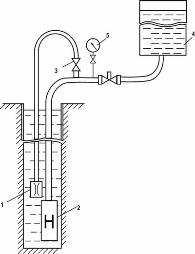
Figure 4.1 – Layout of equipment and tools at the surface and downhole for its mining vibrator driven submersible pump
Recommended criteria of operational management of the cavitation phenomenon well treatment is the speed of fluid flow in vibrogeneratore determined by calculation.
The phenomenon of cavitation in the fluid flow through the hydrodynamic cavitator, can begin when the pressure inside the cavitator close to the value of the saturated vapor pressure. This can be achieved at a certain value of the fluid velocity. Since cavitation flow of water inside cavitator not a continuous medium, and a water-air-steam system, that it has not applied the classical equations of fluid mechanics of continuous media.
Conducted a number of researchers (A. D. Bashkatova, V. S. Alekseev, V. T. Grebennikov and others.) Experimental measurements and analytical solutions demonstrate variable speed (Flow rate) of water along the length of the filter.
Moreover, the maximum flow of water falls on top of the filter. The reason for this is the adoption of flow energetically most favorable shape and path of motion (at a minimum hydraulic resistance).
However, these measurements are valid only for confined aquifers during the installation of the filter pump. In the case of non-pressure horizons measurement data is not valid. Diagrams flow distribution the length of the filter will be different. And changing the position of the zone under study recom – vibrogeneratora installation.
The decisive role in this case as the source Fitting depression – submersible pump. Basic technological schemes of installation of submersible pumps, depending on the geological and hydrogeological conditions given in Figure 4.2. For each circuit diagram constructed water consumption (based on the minimum hydraulic resistance seepage flow).
The degree of influence kolmatatsionnyh processes prifiltrovoy area on production rate and the dynamic water level will manifest itself as much as possible in the areas of greatest water inflow. It is near these areas should be established and cavitation generators. The effectiveness of their regenerative effect in this case will be maximized.
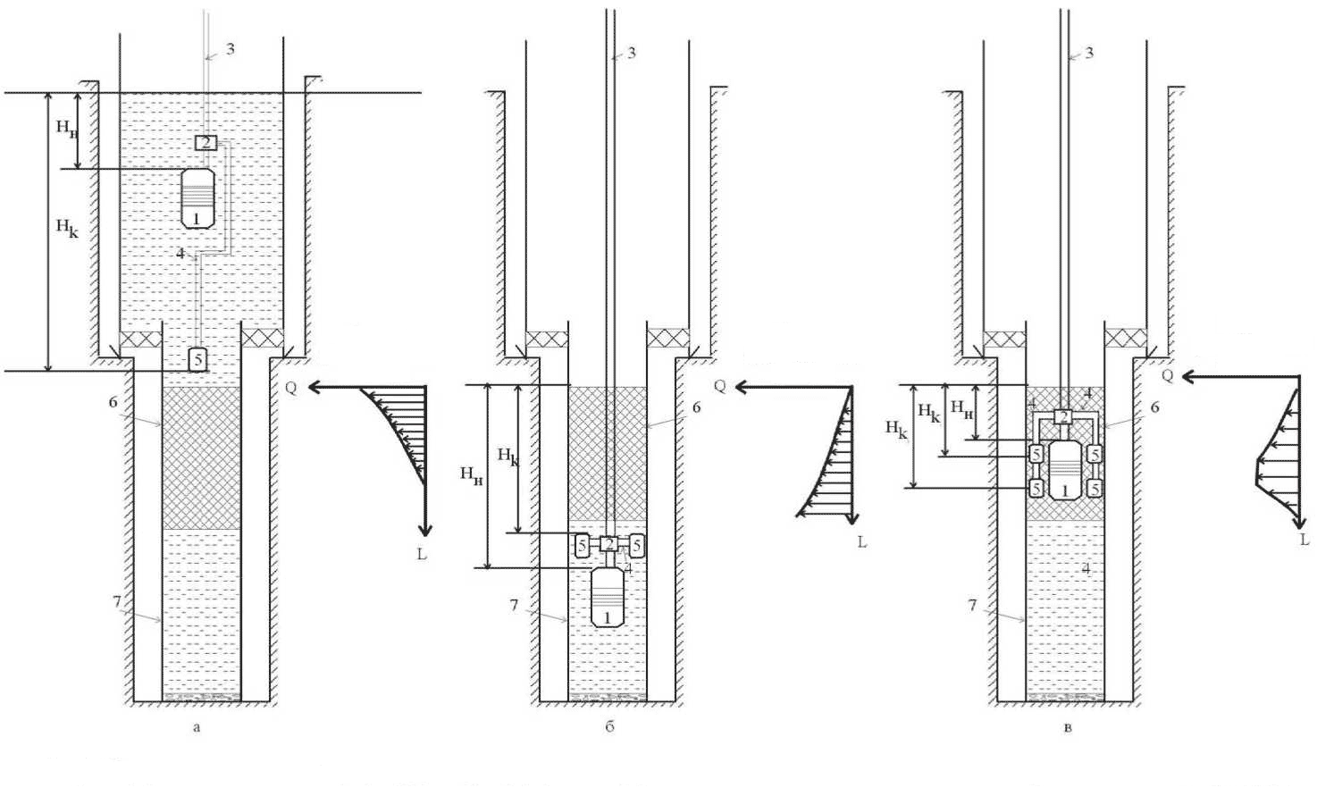
Figure 4.2 – Recommended basic technological schemes of installation of submersible pumps and placing cavitation generators
4.2 Hydraulic device for vibration decolmatation productive formations with small diameter filters
The invention relates to the technical means decolmatation productive formations penetrated by rotary drilling small diameter wells with washing mud and with the installation of filters reduced in comparison with the well-NIJ diameter. Can be used in the development of hydro-geological and geotechnical boreholes.
The technical result is the ability to carry out razglinizatsiyu productive formations penetrated by wells of small diameter, small diameter filters, when placing them at greater depths, while improving cleaning wells from cuttings.
This is achieved in that the device for vibration decolmatation aquifers, including immersion into the well on drill pipe shock pulse generator – hammer or hydraulic hammer – and vibrating unit consisting of the central tube, is rigidly connected to the anvil machines attached thereto disc membranes, rods, whereby the machine body is attached stationary vibratory element assembly, the central tube membranes arranged to reciprocate and biased relative to the machine body, further included is immersed in the well to a level hammers pipe for supplying compressed air, and a vibrating assembly has diameter less than the diameter of the hammers, with the possibility of dipping into a cavity filter, its fixed member located above the membrane and the disc package is designed as a hard disk.
The invention relates to the technical means decolmatation productive formations penetrated by rotary drilling small diameter wells with washing mud and with the installation of filters reduced in comparison with the well diameter. It can be used in the development of hydro-geological and geotechnical boreholes.
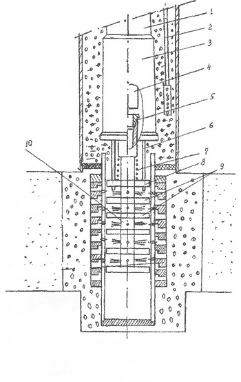
Figure 4.3 – Diagram of hydraulic decolmatation
5. Description designed mechanism
A device for razglinizatsii productive strata, which includes hydraulic hammer and join vibrating unit.
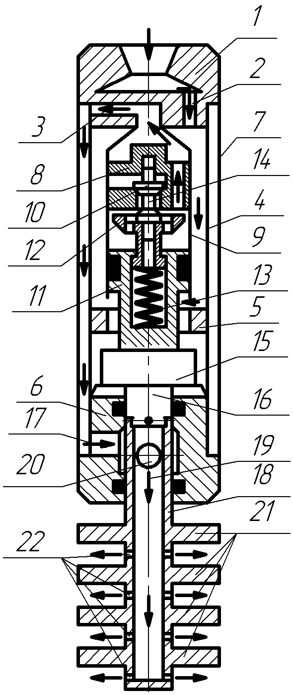
Figure 5.1 – Diagram of the hydraulic decolmatation
The composition includes hammers dispensing adapter 1 with an inlet 2 and outlet openings 3. Distribution adapter 1 is connected to the upper housing 4 and lower 5 6 anvils and housing 7 – the lower anvil 6. dispense adapter 1 is attached to the valve box 8 cylinder 9. The valve box 8 and the inlet valve 10 is located. 9 is placed inside the cylinder piston 11 in which the exhaust valve 12 is mounted with a spring 13 connected to the intake valve 14. The piston 10 pusher 11 is connected with the striker 15 at the bottom which is made rod 16 mounted on the lower anvil 6, wherein a radial passage 17 connected to the gap between the housing 4 and the housing 7.
The structure of the vibrating tube assembly 18 includes an axial passageway 19 and radial hole 20 are attached to the pipe 18 of the membrane disc 21, between which openings 22 are made. The pipe 18 is connected to the rod 16.
The device operates as follows. It is lowered into the well on drill pipe, which fluid under pressure is fed into the control adapter 1 passes into the inlet 2 and further through an annular gap between the casing 4 and the cylinder 9 extends into the cavity of the cylinder 9 below the piston 11. This inlet valve 10 is closed and the exhaust valve 12 is opened. Under pressure fluid in the subpiston space 11 of the cylinder piston 9 begins to move upwards, while the exhaust valve 12 pushrod 14 is supported in the inlet valve 10 remains in place, which leads to compression of the spring 13. Fluid above the piston with the cylinder cavity 9 through exhaust passages of the valve case 8 passes through the outlet 3 to the annulus between the casing 4 and the housing 7 and then through the radial passage 17 in the lower anvil liquid 6 through the openings 22 in the central tube extends into the shell side of the well. The piston 11 continues its movement and strikes the exhaust valve 12. In this case, due to the impact energy and under the force of the spring 13, the pusher 14 is passed, the inlet valve 10 opens. The piston 11 continues its movement by inertia, and the exhaust valve 12 by the spring 13 closes exhaust passages in the valve box 8. The striker 15 connected to the piston 11, moving with it strikes the upper anvil 5. The pressure above the piston and the cylinder subpiston 9 becomes the same, but, due to the fact that area of the piston top 11 is more than an area below the value of the square rod 16, there is a force which causes the piston 11 to move downward. The liquid is passed to the cylinder space above the piston 9 through the open the inlet valve 10 and outlet channels 12. The valve piston 11 moves downward, and the outlet valve 12 remains closed until the piston 11 will strike the projection in its lower part. Then the exhaust valve 12 will come off of the valve housing 8, and will move down. Thus the intake valve 10 closes. The piston 11 continues to move by inertia, and the striker 15 strikes the lower anvil 6. Next cycle of operation is repeated.
Due to the fact that the vibrating unit is connected to the rod 16, it has the possibility of reciprocating movement in the borehole. Thus it ensures the generation of pressure waves in the liquid, which influence borehole wall, clearing them from clay and other sediments. The liquid that comes out of the holes 22 also contributes to a better purification of the borehole walls. Shock pulses which are transmitted to the disk 21 of the membrane, enhance the frequency of the pressure waves, which also has a positive effect on the process razglinizatsii reservoirs.
Figure 5.2 – The principle of operation of the apparatus
(Animation: volume – 97 kb.; number of frames – 4; time delay – 0.5 s.; reps – 7)
Findings
The review of existing technologies and means to combat clogging wells. Based on the review determined that the work will be carried out towards the establishment of mechanisms that combine two kinds of means: cavitation generator and a device excited oscillations of fluid pressure in the well with the help of hammers. A diagram of the device.
List of sources
- Цейтлин М. Г., Верстов В. В., Азбель Г. Г. Вибрационная техника и технология в свайных и буровых работах. Л.: Стройиздат, 1987.
- Восстановление дебита водозаборных скважин в процессе их эксплуатации // Материалы VII Международной научно-практической конференции: Наука и нвейшие технологии при освоении месторождений полезных ископаемых. М.: МГГРУ, 2005. – С. 294 / соавторы Сердюк Н. И., Хромин Е. Д.
- Ратов Б. Т., Кудайкулов С. К., Касенов А. К., Федоров Б. В. Устройство для вибрационной разглинизации водоносных пластов Пред. патент №14693. РК.
- Ратов Б. Т., Федоров Б. В., Танатаров Т. Т. О классификации способов освоения продуктивных пластов // Вестн. Каз НТУ им. К. И. Сатпаева. – 2007. – № 2 (59). – С. 22–25.
- Дудля Н. А. Проектирование буровых машин и механизмов: учебник для вузов / Н. А. Дудля .– К.: Выща школа, 1990. – 272 с.: ил. + прил. – ISBN 5-11-002313-1.
- Поляков Г. Д., Булгако Е. С., Шумов Л. А. Проектирование, расчет и эксплуатация буровых установок / К.: Недра, 1983.–317с.: ил. + прил.
- Гидробур – Патент СССР 07.05.1982 – SU 926210 / База патентов СССР.