
Abstract on the final work
The contents
- Introduction
- 1. Aim and problems
- 2. Actuality of the topic.
- 3. The main part
- 3.1. Purpose and classification of AR
- 3.2. Basic requirements to AR
- 3.3. The ground for the AR using
- Conclusions
- The list of sources
Introduction
Automatic reclosure (AR) is one of the main means of reliability increase of power systems operation and consumers uninterrupted power supply in modern power systems. Long experience has shown that a significant number of violations of insulation installations in general and overhead lines in particular, is unstable and selfremoves without voltage. Such damages arise as a result of lightning flashover of insulation, electric cross at the wind and dropping ice, falling trees, touching of lines by moving machinery (cranes, stacker). If the duration of protection relays is small, the electric arc, resulting in violations of the insulation, does not have time to cause significant damage (burn-out wires, complete destruction of the insulator) and restartable line remains in operation, i.e. there is a successful reclosure. Permanent damage such as broken wires, shorted wires by ground wire, breakage and tower falling, occurs much less frequently. In these cases, the reclosure is unsuccessful, the line is again turned off by relay protection [1].
1. Aim and problems
The aim of this work is evaluation of the effectiveness and feasibility of AR application as a means of automatic emergency control in electric power systems, creation a mathematical model of the network site in software environment Mathcad and performation the tasks.
2. Topic actuality
Nowadays with intensive growth of energy consumption in industrial and other objects, there is a need in their reliable and efficient electric power supply. The automatic reclosure devices decide this task perfectly [7]. As the AR will quickly eliminates the interruption of the mains supply at short-circuit in single power supply lines with a pick-up motor load. The serious violations of the technological process of consumers are prevented. The number of switches in distribution lower voltage networks reduces. The consequences of incorrect or spontaneous disconnection switch decreases, and the possibility of relay protection speed occures.
3. The main part
3.1. Purpose and classification of AR.
The AR is intended for line or separate phases switch after their disconnecting as a result of relay protraction action or on other reasons (except for disconnecting by duty staff). The AR is provided for rapid renewal of feed by the fast automatic switch of circuit-breaker QF, disconnected by the relay protection and automatic devices. The AR is necessarily for all of overhead transmission and cable lines at voltages from 1 to 35 kV, and higher 35 kV – by a project.

Figure1 – Block diagram of the AR
(animation: 4 frame, 20 cycles of repetition, 51,7 KB)

Figure 2 – A schematic diagram of the AR
The AR should operate so that it did not act at disconnecting QF by duty staff locally or distantly [10].
Automatic reclosure is classified by five fundamental characteristics:
- Protected equipment: AR transmission lines, AR motors of 6 kV, AR transformers, AR bus-bar [8];
- Single-phase AR or three phases AR. It is depended from the numbers of the operating phases;
- The number of AR operations single or multiple action;
- According to the method used for synchronization [9]:
- without checking of synchronization (in this case synchronism violation of is excluded);
- when appearance of AR asynchronous is acceptable;
- without synchronism checking, when there are high-speed switches and relay protection;
- AR with the waiting of synchronism;
- AR with the trapping of synchronism;
- AR, combined with the synchronization of generators and synchronous compensators.
- Depending on the action to the switch driving, mechanical AR with a direct action [2].
3.2. Basic requirements to AR
- The AR has to operate accordingly to the established time lag, after action should return to a state of readiness for the new operation [3].
- The pulse duration, reaching to switch on it is need to ensure a reliable switching on of the equipment;
- AR should not be switched on at the operational switches in any rapid order, including the signals for the remote control;
- At the steady short-circuit on line or any other section of the scheme the multiple action of AR should be excluded;
- Schematic of the AR devices must have locking devices from other anti-emergency automac and relay protection, such as frequency load shedding and transformer protection against internal damage;
- The AR device needs to be provided the subsequent setup for accelerated action protection before or after AR [4].
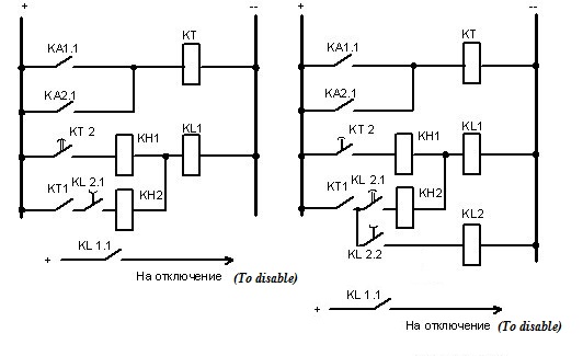
Figure 3 – The scheme of accelerated action protection 1 – After AR, 2 – before AR. The operation of the circuit is due to the action of relay acceleration KL2.1 type RP-252
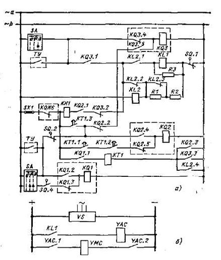
Figure 4 – AR diagram of the transformer used for high-voltage load switch with an electromagnetic action driving from 6/10 kV side, operating with alternating operational current: a – schematic diagram of automatic reclosure device, b – scheme of elements of the trip circuits
The two-step relay fixation 12РП is a lock from multiple actions, the output relay 11РП relates to circuit AR and serves to separate the AC and the rectified currents circuits, and is indented to turn the contactor switch drive [5].
The electromagnet of inclusion is powered by the rectifier unit, the relay contacts 11РП are included in pairs in series and parallel to increase values of breaking capacity as in the circuit of the contactor windings have a large inductance at the voltage value of 300 V.
3.3. The ground for the AR using
The ground for the AR using Is considered the equivalent circuit of Fig. 5,a, where two parallel lines connect the deficient subsystem I with subsystem 2 with significantly more power. The aim is to provide the stability at a short circuit on one of the lines. As a means of emergency control are discussed the high-speed AR of the line (BAPV) and load disconnection [6].
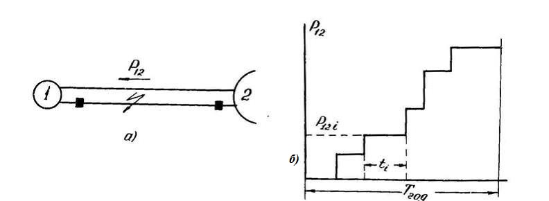
Figure 5 – Equivalent circuit and load schedule
The initial data: annual load cirve of the transmission line Pi = f(ti) (Fig.5,b), the mathematical expectation of number cases of short circuits cases on transmission lines is n, the probability of unsuccessful AR – T, the duration of currentless pauses for load AR - tАR, average duration of load shedding without BAR – t0, specific damage of the consumer at disconnection it for a time t0 – η0, and short-term off at the time of tАRВН – ηА. It is assumed that in case of successful BAR for all values of Pi the stability is keeped without the use of additional measures.
Three variants of emergency actions are compared:
- BAR is not applied, if it is necessary , the load disconnection is used for stability providing.
- BAR applies, if BAR is unsuccessful, load disconnection is used.
- BAR and load disconnection apply simultaneously, and in case of successful BAR the load AR is executed.
To simplify the problem, the damage will be determined without taking into account the possibility loss of stability due to the failure of load disconnection. The result of the calculation of transients in each i-th load mode (Pi) under the condition of the calculated (the most hard) short circuit the values for the minimum required power of disconnected loads 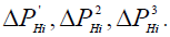 are determined in each of the three variants.
The annual damage in each of the variants is calculated at expressions:
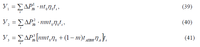
From general considerations it is obvious that 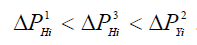 For some the i-th mode can be based by the comparison of (39–41) to set the the inexpediency of BAR application in the form of the conditions:
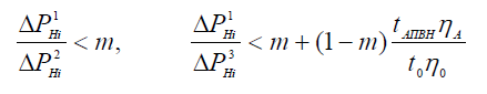
which after transformations are formed to:
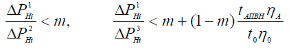
The BAR application obviously unreasonably, if these ratios are correct in all calculated modes. In other cases, it is necessary to calculate and to compare conditions 1 and 2, 1 and 3 and only if 1 < 2 and 1 < 3 can be argued that the use of BAR is unreasonably. To establish priority of one of the two considered variants for the load disconnection control at the BAR application it is necessary to determine the ratio 2 and 3, calculated according to (40), (41).
Conscutions
Made analysis in the job showed that the AR use in electric power systems as a means of automatic emergency control, can significantly improve the reliability of the power system. In addition, in some cases, the AR allows to avoid serious consequences from erroneous actions of duty staff or misoperation of relay protection on the protected area.
Remarks
At the time of writing this essay master's work is not yet complete. Estimated completion date: May 2017 The full text of work and materials on the topic can be obtained from the author or his manager after that date.
The list of sources
- Голубев М. Л. Библиотека электромонтера / Автоматическое повторное включение в распределительных сетях – Энергоиздат 1982, c. 3-4 [Электронный ресурс]. – Режим доступа:http://www.proektant.org/books/0059-ELE-1982.pdf
- [Электронный ресурс]. – Режим доступа: http://enargys.ru/avtomaticheskoe-povtornoe-vklyuchenie-apv/#prettyPhoto
- «Библиотека электромонтера. Автоматическое повторное включение» Овчинников В. В. М. Энергоатомиздат 1987 – 410 с.
- «Автоматика энергосистем» 3-е издание, переработанное и дополненное Беркович М. А., Гладышев В. А., Семенов В. А.. М. Энергоатомиздат 1991 – 385 с.
- «Релейная защита энергетических систем» Чернобровов Н. В., Семенов В. А. Энергоатомиздат 1998 – 292 с.
- Кощеев Л. А. Автоматическое противоаварийное управление в электроэнергетических системах, УДК 621.311/621.316 – с. 94 -96.
- [Электронный ресурс]. – Режим доступа: http://vunivere.ru/work32056.
- [Электронный ресурс]. – Режим доступа: http://dororz.ru/.
- Автоматическое повторное включение/ Овчинников В. В./ Энергоатомиздат – 1986 – 96c.
- [Электронный ресурс]. – Режим доступа: http://leg.co.ua/knigi/rzia/releynaya-zaschita-i-avtomatika-v-elektroustanovkah-2.html.