
Content
- Introduction
- 1. Formulation of the problem. Review mechanisms
- 2. Structure of industrial robot
- 3. Lifting / lowering system
- 4. Conclusion
- List of sources
Introduction
In the steel industry in particular in the production of high-quality steels are widely used converters and ladle furnace. The resulting steel at these plants is bottled in special buckets which then should be a continuous casting machine or casting mold. Steel from ladle to tundish flows from the tundish via a special glassful into the mold. For the glassful is supposed to use a robotic complex. This complex is currently being tested in a laboratory layout of the department of mechanical equipment of ferrous metallurgy plants (ŃŃM). The laboratory setup is made in scale 1:2 (with respect to the intended industrial design) on the unit received a patent CCM department. Department CCM proposed the development of electric drive systems for the two mechanisms robot of the complex is a glass of installation mechanism (cleaning) glass hoist/lowering manipulator platform.
In this project focuses on the mechanism of lifting (lowering) the manipulator platform.
At the first stage it is planned to analyze the mode device, select the drive motor and the drive system. In the second stage, after purchasing and installing the components in the drive and control system is expected to produce experimental studies and to identify the main strengths and weaknesses of the used drive.
1. Formulation of the problem. Review mechanisms
Modern highly mechanized and automated production is impossible without the use of industrial robots (IR), flexible automated production (FAP), processing units or centers.
The first industrial robots appeared in the US in 1959, when the robots have been created with program management. In 1962, the use of robots found their Unimate
, Versatran
for maintenance of casting processes, forging, machining, spot welding, painting. The cost of the first robot was 25–30 thousand dollars per unit. In the automotive and steel industry payback period was 1.5–2.5 years, which was quite high for the time.
It is interesting to note that in the magazine Machinery Magazine
published an article about a new type of worker who does not drink coffee or smoke, is open 24 hours a day and is not a member of a union. The word work
(corvee, forced labor) was used by the Czech writer Karl Capek in the play RUR (Rossum Universal Robots, January 1921).
It quickly migrated to the technique and has been used as a common noun for those mechanisms that perform heavy, monotonous work. This mechanism class and was named robots
. The advanced countries are beginning to release the active PR in the struggle for markets. In the first place in the design, manufacture and implementation beyond Japan. The dynamics of growth in output PR can be seen in the following numeral : in 1978, there were 16,000 PR, in 1980 in the world – 25,000 in 1983 – in the capitalist countries – 31000 pieces.
According to preliminary data of the Soviet Union in 1983 there were about 7000 OL and OL planned to bring the number to 375 thousand pieces by 1990. Japan continues to hold the championship for the design of new types of robots. Much attention is paid to the creation of so-called humanoid robots, repeating human movement, designed and manufactured specialized robots to help people with impaired hearing, the musculoskeletal system.
2. Structure of industrial robot
The practice of such devices in a number of foreign and domestic metallurgical enterprises showed that the effectiveness of their application increases significantly if they are working in conjunction with the manipulators, providing mechanized feeding to the receiving guides tundish tundish preheated to the required temperature reserve of refractory products, which should be for the fraction of a second under the influence of the power cylinder to replace the faulty glass.
The variety of schemes the relative position of the equipment of modern continuous casting machine and the peculiarities of its functioning are the main prerequisites for the development of quick-change systems, submerged nozzles, which is best suited to the conditions of continuous casting of metal concrete steel plant. The department Mechanical equipment of factories of ferrous metallurgy
, Donetsk National Technical University in the last 5 years have been patented and designed several types of systems that allow virtually without interrupting the casting to replace a submerged nozzles, jet screening began at the site tundish – mold slab caster.
Manipulator, a part of these systems, is located on-site by the end of the tundish. This scheme relative placement of the manipulator fully meets the conditions of casting steel caster single-strand intermediate buckets which are translated into the working position using the tilt–table. On machines with a large number of streams carried replacement tundish is known to use self–propelled trolley that moves in the direction of its longitudinal axis. In this case, the manipulator is an obstacle to moving the cart, making it difficult to use.
In connection with this new design scheme (Fig. 1) I was offered steady arm, which can eliminate this deficiency.
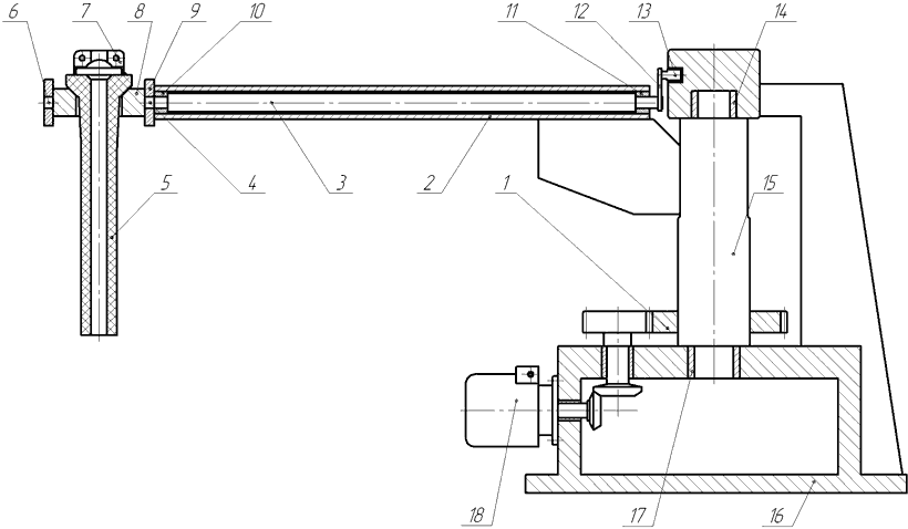
Figure 1 – The scheme developed by the system quickly submerged nozzle changer
The manipulator comprises a base 16 on which is mounted rotating column 15 mounted on the bottom 17 and top 14 of fixed bearing supports and equipped with two horizontal hollow bracket rigidly associated with the platform 9. The platform actuating cylinder 7 is placed on the trunnions 4 and the fixed bracket 6 8 carrying a replaceable submerged nozzle 5. The bracket 8 is pivotable in a vertical plane with respect to the hollow console via a mechanism including a transmission shaft 3 is mounted within console bearing supports 10 and 11 and the holding at the end facing the rotary column 15, arm 12 equipped with a roller 13 placed in a shaped guide groove formed on the outer cylindrical surface of the housing upper fixed pivot bearing assembly 14 column. The other end of the transmission shaft is rigidly connected with pin 4 supporting bracket 8. The lower part of the column 15 is provided with a rotary ring gear 1, through the gears associated with the electromechanical actuator 18 fixed to the base 16.
The principle of operation of the proposed system quick change of submersible glasses explains Figure 1.3. During continuous steel casting manipulator is located in the initial position in the platform 19 to the tundish 20, 21 equipped with a tundish provided with a protective glass 22, the lower part of which is immersed in the melt located in the mold 23. In this position the rotating column 15, the horizontal carrier arm 2 and the bracket 8 installed therein a replaceable submerged nozzle 5 occupy the relative position shown in Fig. 2a. In this interchangeable glass 5 is held horizontally and the clamps supporting bracket 8 deployed in a platform recess 9. Fixing bracket with glass relative to the platform 3 provided with a transmission shaft, which arm 12 to its roller 13 located in a shaped guide groove, the mechanism holds said elements in position.

Figure 2 – The sequence of operation quick change of submersible glasses
To replace the submerged nozzle must enable the actuator 18 which through gears and crown 1 performs rotation column 15 in top 17 and bottom 14 of fixed bearing supports. At the column is horizontally rotatable hollow arm 2 and arranged inside it in bearing supports 10 and 11 of the transmission shaft 3 with an attached lever 12. The roller 13, rolling on one of the surfaces of the shaped guide groove formed on the outer cylindrical surface of the upper fixed support 14 acts at the end of the lever 12, turning the transmission shaft 10 and bearings 11 about a horizontal cantilever 2. The rotation shaft 3 is transmitted through pin 4 yoke 8 which carries rotation relative to the platform 9 replaceable submerged entry nozzle 5 (Fig. 2.3b) to complete its transfer to the vertical position. This transfer is completed at the approach to the glass end of the tundish 21, and its location in alignment with the guide. Thereafter, the power cylinder 7 located on the platform 9, the backup glass 5 is moved along the guides of the tundish 21 as long as it does not take the place of the failed the immersion nozzle 22, a shielding stream steel flowing from the tundish 20 into the mold 23 (Fig. 2.3v). Cup travel speed such that the process of change lasts for 0.2–0.3 sec, i.e. virtually without interruption of the jet liquid steel. Substituted casting nozzle is removed from the tundish guide grooves with a special device, and the console handler returns to the initial position by rotating the column in the opposite direction. In the initial position of the manipulator design elements do not interfere with the movement of the trolley with the tundish at an emergency congress or in the case of a transfer ladle at a repair site for the replacement of its lining.
In the design of the industrial design of the proposed system of quick change of submersible glasses, previously developed methodology for calculating energy-power parameters of drives of mechanisms included in its composition: the combined electromechanical providing simultaneous rotation of the column with the console in the horizontal and removable cup in a vertical plane, as well as hydraulic, performing accelerated movement PR and the new glasses on the reference guide tundish.
3. Lifting / lowering system
Why do we need a system for lifting / lowering manipulator? In the modern system technology tundish CCM is regarded as one of the most important elements, which have a direct impact on the quality of continuous casting.
In the chain of technological spillovers tundish is buffering capacity, as agreed upon with the help of metal flow from ladle into the mold. Thus provided metal entering averaging portion and preventing slag entering the crystallizer. It is assumed that the tundish design should ensure minimum heat loss metal.
Tundish provides the metal flow into the mold with a certain flow rate and providing a well-organized stream, allowing pouring steel into several molds at the same time to carry out serial casting method of melting in the melting ladle when changing without stopping and reducing the casting speed. The design capacity of the tundish and largely determine the stability of the casting process and the quality of the workpiece.
The reasons for changing the vertical position: 1. Go to a different section of the ingot casting. There is a changeover section of the mold and change of position ladle. 2. When you go to casting other types of steel (other chemical. Composition of the steel). Changing the position of the ladle of the need to generate corresponding new steel grade of the hydrodynamic flow in the mold caster. Changing the ladle position is carried out hydraulically.
Arm lifting / lowering system allows to adjust, with the help of an induction motor, the structure of the minimum time, as well as to establish the intermediate glass in the groove with a minimal loss in production.
Figure 3 – Animated display of the work of the manipulator (5 frames, 6 cycles of repetition, 157kb size)
4. Conclusion
This project has already received positive reviews from leading professors of Donetsk National Technical University, as well as the uniqueness of the manipulator was marked by a variety of countries (China, Russia, Poland and etc.).
Asynchronous motor with squirrel cage was selected to automate system recovery/lowering manipulator platform. To fully automate the system is using circuit FC–AD to control the drive (frequency converter – induction motor). It will be implemented tracking system actuator that provides tracking of the position of the tundish during the casting of steel.
At the time of writing this abstract of master's work is not yet complete. The estimated date of completion of the master's work: June 2017. The full text of work and materials on the topic can be obtained from the author or his manager after that date.
List of source
- Dyudkin D. A., Kisilenko V. V., Production of steel, Vol.1 The processes of smelting, secondary metallurgy and continuous casting, M .: Heat engineering, 2008. – 528 p.
- Introduction to the profession. V. F. Borisenko – Donetsk, Donetsk National Technical University, 2014. – 357 with.
- Eronko S. P., Bykovskikh S. V., Steel casting equipment. Technology. & Ndash; C. Technical. 2003 – 216s.
- Wikipedia, the free encyclopedia https://ru.wikipedia.org/wiki/....
- Ukraine Patent 96891, Â22D41/56, Â22D11/106. Pointing to replace submersible glass on the slab continuous casting machine / S. P. Yeronko, M. Y. Tkachev, K. V. Duboyskyy; Donets. nat. Sc. Univ. & Ndash; ą2010155511; 23.12.2010 stated; publ. 12.12.2011, Bull. ą23. & Ndash; 5 p.Patent 96891.