
Research and development of measures to improve the reliability of electrical networks in own needs of power stations
Content
- Introduction
- 1. Relevance of the subject
- 2. The purpose of the research
- 3. Present state of research of arc overvoltage in networks of
6–10 kV and the foundation of research methods - 3.1 High–resistive grounding of neutral network of 6 and 10 kV
- 3.2 Low–resistive grounding of neutral network of 6 and 10 kV
- 3.3 Combined neutral ground in networks with 6 kV and 10 kV voltage
- 4. Mathematical model for the study of transients in networks of TPS
- Conclusions
- List of sources
Introduction
By the rules of electrical devices (RED) [1] operating mode of electric networks is set with voltage of 6 kV and 10 kV with isolated neutral or compensated neutral.
The most common type of damage in such networks – single-phase ground fault with intermittent arc, constituting more than 70 % according to [2]. Emerging with the multiplicity of the arc overvoltage up to (3–4)UP dangerous for electrical equipment, primarily for high–voltage electric motors, generators, cables and voltage transformers according to [2–5].
1. Relevance of the subject
The use of neutral grounding resistor allows to get rid of dangerous surges and increases the speed and selectivity of relay protection.
The occurrence of arc overvoltage mostly connected with intermittent arc and relatively small currents SPGF (single-phase ground fault), not exceeding 10 A. The value of the amplitude of the surge at the same time can reach 3.5–3.8 phase voltage UP. By increasing the current SPGF arc overvoltage are reduced. This is due to the fact that the arc has an even temper, and does not cut off at high currents. At currents SPGF from 10 to 20 A overvoltage does not exceed 3UP. At currents SPGF from 20 to 50 A overvoltage does not exceed 2,7UP.
The parameters of the transition process in the event of single–phase arcing fault in networks with isolated or grounded neutral through ASL (arc suppression lattice) determined by the capacity of the phases, the inductive resistance of the power source, transformer and ASL, as well as arc resistance. The main factors determining the maximum overvoltage at GF (ground fault) are: voltage on the emergency phase at the time of the initial ignition of the arc Ui, the moment of arc extinction and re-ignition voltage of the arc Uri.
2. The purpose of the research
The purpose of the research: the development of a mathematical model and investigation of transients at arc fault phase on the ground in distribution grids of
Object of the research: electromagnetic transients at ground faults in networks of
Subject of the research: the parameters of arc overvoltage to ground faults in networks of
Methods: during the research position of the electromagnetic field theory are used in electric circuit theory. To estimate the influence of neutral grounding modes on the parameters of arc overvoltage mathematical model of electromagnetic transients is applied. Model of electromagnetic transients in the electrical network is obtained using the method of the phase coordinates. To develop the network model structural simulation method is used.
3. Present state of research of arc overvoltage in networks of 6–10 kV and the foundation of research methods
3.1 High–resistive grounding of neutral network of 6 and 10 kV
The main purpose of high–resistive grounding of the neutral network is to limit the arc overvoltage and ferroresonance phenomena, while ensuring long-term operation of the network with the GF on search time and turning off the damaged connection with operational staff. Reducing of voltage on the neutral and surge suppressor with arc fault to ground is achieved by reducing the time constant of the discharge capacity of the working phases during the dead time tP via specially connected resistor RN (Fig. 1), which provides a decrease in flow resistance circuit residual current. Resistor RN connects to the network via the transformer with the connection scheme of windings Υ/Δ in one of two ways.
The first method – a resistor connected between the neutral point of the winding of high voltage TDM and circuit ground (Figure 1a.).
The second way – neutral high voltage winding CP (current protection) connected to ground, and the resistor is switched to the secondary winding of the transformer in open delta (Figure 1b.). Connection of the resistor is determined by the network structure and parameters of the installed equipment.
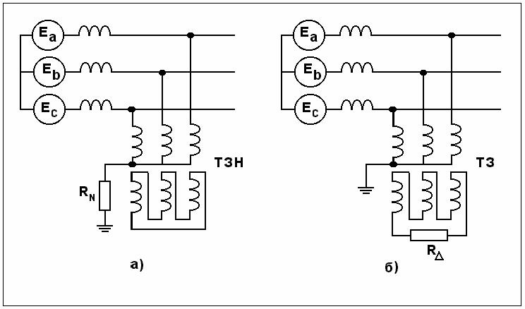
Figure 1 – Connection scheme of the resistor to neutral of the network
To ensure the complete discharge of phase tanks during tP, which is equal to 0.008–0,010 s, the resistor is selected such that the active component of the ground fault current IR is equal to or greater than the capacitive component IC

From this condition, the resistor for the circuit Fig. 1а, RN, Оm, calculated by the formula:

and the resistance of the resistor to the circuit in Figure 1b, and the resistance of the resistor to the circuit in Figure 1b, RΔ, Оm, calculated as follows:

where UHL – line voltage of the side of the higher voltage, V;
IC – capacitive current PTG, A;
K – CP transformation ratio, calculated according to the formula:

where ULL – line voltage side of the transformer low–voltage, V.
Rated power of the transformer neutral grounding resistor and RN or RΔ, S, VA, calculated as follows:

The value of the current flowing through the resistor SPGF mode for the circuit of Figure 1a, IR, A, is calculated according to the formula:

The value of the current flowing through the resistor for the circuit of Figure 1b, IΔ, А, is calculated according to the formula:

The current I(1) is in place SPGF geometric sum of the capacitive network and current of the active current generated by the earthing device. The current value I(1), А, is calculated according to the formula:

and using the formula (1):

By increasing the resistance of the resistor in comparison with the value calculated by formula (2), the voltage at the neutral point for the currentless pause is not reduced to zero but to a specific value ΔUN, which increases the level of arc overvoltage KP
The value of resistor calculated according to the formulas (2, 3), is redundant for power dissipation. More specifically, the resistance of the resistor in the neutral phase providing containers for the discharge time tP is calculated taking into account the active losses in the network based on the magnitude of the fault current to the ground and reducing the required level of arc overvoltage. The calculation is made on the specialized program for calculating electromagnetic transients in accordance with [13, 14].
3.2 Low–resistive grounding of neutral network of 6 and 10 kV
The main purpose of low–resistive neutral grounding resistor network is fast tripping SPGF relay protection and maximum coverage of the windings of electrical machines (motors, generators, transformers) protection of SPGF. It also provides surge suppression and ferroresonance phenomena.
Low–resistive grounded neutral network is carried out using a special TDM grounding transformer neutral connection with the scheme Υ/Δ, windings, as shown in Fig. 1a. Resistor RN is turned on between zero point HL winding and ground loop.
Resistor is chosen the least, on the basis of two conditions:
- Prevent surge at SPGF (2), the resistor must create a current of at least capacitive current SPGF;
- providing selective operation on protection of tripping SPGF.
Selective shutdown can be achieved by connecting the neutral resistor networks with resistance, calculated by the formula:

where IS.Z. МАX – maximum tripping current at SPGF.
Chosen by these conditions resistor typically creates the active current significantly exceeding capacitive. If the capacitive current is much less active IС << IR, the current SPGF can be calculated by the formula:

where UN – linear voltage.
At SPGF in the winding connected in star, SPGF current IZ, A and considering (11) is calculated according to the formula:

where W – the number of loops of the stator winding of the clamp circuit to the point, percent of the total number of loops of the faulty phase.
For winding connected to a triangle, the smallest fault current at the midpoint of the housing IG, windings, A, is calculated according to the formula:

At SPGF in the windings of high–voltage motors to prevent burn–active steel stator fast tripping of the motor protection against ground faults should be provided.
The number of windings of the protected SPGF W, %, calculated as follows:

where ISZ – tripping current from SPGF, A.
IR – current grounding resistors, A.
We can enhance protection by increasing the active current resistor, or reducing the tripping current within acceptable values, the calculated sensitivity factor protection.
Depending on the method of selection of the grounding resistor and the current value of SPGF grounding transformer for low-resistance grounding resistor network neutral and resistor must be calculated either on a short-term or the long-term work in SPGF mode, during which shall be no excess of normalized temperature parameters.
Tripping current connections from SPGF ISZ, A, calculated by the formula:

where KH – reliability coefficient taken equal to 1.2;
KB – coefficient taking into account the capacitive inrush current;
IC – capacitive current RCT (residual current transformer) protected connection with the SPGF section on indoor switchgear – 6 kV and 10 kV.
In the event of an extended mode of SPGF (eg, in case of failure in the protection), the protection of the residual OPR (overcurrent protection residual) delayed effect on the OPR switch off, thereby transferring network with isolated neutral mode. If the OPR switch is switched off, this protection may act to trip the circuit breaker and the input section switch (if enabled).
3.4 Combined neutral ground in networks with 6 kV and 10 kV voltage
The resistance value of the resistor R*N, Оm, allowing to eliminate the beats are selected based on the ratio:

where ΔI – current mismatch compensating reactor, A.
Determined by the formula (17) of the resistor R*N, resistance value connected in parallel coils, leads to a complete elimination of the beat after the arc extinction and reduction of surge in repeated breakdowns to UМАX ≈ 2,4UP. However, most of all, the power of the resistor is redundant.
Clarification of the resistor values can reduce overvoltage to a predetermined value, it is carried out by means of calculation, taking into account all the influencing factors on the specialized programs set forth in [13, 14]. In this case, the resistor parameters are calculated for:
- surge suppression mode SPGF to a predetermined value КP (usually up to the level of the test voltage when preventive tests of rotating machines);
- stresses the limitations encountered in the neutral in normal mode due to the asymmetry parameters of the circuit;
- increasing the active component of the earth fault current to a level that provides a selective operation of protection on the current principle;
- elimination of dangerous ferroresonance phenomena.
At connection in parallel with the resistance of the resistor ASL:

maximum surge does not exceed the level UМАX ≈ 2,6UP.
4. Mathematical model for the study of transients in networks of TPS
For the analysis of transients in networks own needs of TPP at arc short circuits on the ground is taken as the basis of power supply circuit TPS shown in Figure 2.
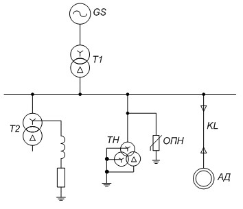
Figure 2 – Scheme of electricity supply of TPS own needs (Thermal power stations)
In drawing up the scheme of substitution, given the relatively small length of the cable connections for the auxiliary power conditions (0,5 km), we can accept for all the elements focused on network settings. We will also consider the network in the research as a linear, i.e we neglect the saturation of the individual elements. Based on the above Figure 3 shows the equivalent circuit of the test network, adopted as the basis of a mathematical model.
Figure 3 – Equivalent Circuit own needs
(Animation: 5 frames, 10 cycles of repetition, 152 kilobytes)
Conclusions
The main results are as follows:
1. The main reasons of the high damage of electrical equipment in medium voltage class are arc–voltage, resulting in intermittent nature of the arc at the site of the breakdown phase insulation to the ground.
2. The problem of improving the reliability of distribution networks operation of
3. An effective solution to the problem of improving the reliability of distribution networks operation of
*This master's work is not complete yet. The full text and materials can be obtained from the author or his research manager in July 2017.
List of sources
- Electrical Installation Regulations. Div. 1 "General Rules". Approved. Order Dept. of Energy from 08.07.2002 number 204 "On approval of the Rules of the heads of electrical devices." – SPb.: DEAN, 2002. – 176 p.
- Kostenko M., Bogatencov I., Mikhailov Y., F. Khalilov. Overvoltage at arc ground faults, enabling or disabling of inductive elements. – Results of science and technology / VINITI. – T. 17. – 105. (Electr. Stations and networks).
- Guidelines for the protection of electrical networks 6–1150 kV against lightning and internal overvoltage / under scientific. Ed. N. Tikhodeev. – 2nd ed. – SPb.: PEIPK Ministry of Energy of the Russian Federation, 1999. – 153 p.
- V. Zilberman, Epstein I., Petrishchev A., Christmas G. Influence of a way of grounding the neutral network needs its own block of 500 MW in the surge and relaying. – M.: Electricity, 1987. – № 12.
- Vasyura Y., V. Gamilko, Evdokunin G., N. Utegulov Surge protection in networks of
6–10 kV . – M.: Electrical 1994. – № 5/6. - Volume and electrical testing standards: RD 34.45–51.300–97 / Ed. B. Alekseeva, F. Kogan, L. Mamikonyants. – 6 th ed. – M.: NTSENAS, 1998. – 256 p.
- Sirota I., Bogachenko A., Kanevsky Y. Experience protection ground fault circuit stator generator, working directly on the busbars, and high–voltage motors. – M. – Electric Power Plants, 1993. – № 7.
- Partial neutral grounding in electrical networks
6–10 kV : CPU–980–89 / Mingazprom, PA "Soyuzorgenergogaz" SU "Lenorgenergogaz" 1989. - Evdokunin G., Goodilin S., Korepanov A. The choice of neutral earthing in networks of
6–10 kV . – Electricity. – № 12, 1998. - On improving the reliability of networks 6 kV own needs NPP: (Circular 01–97–C (O)). – M.: Rosenergoatom 1997.
- Guidelines to improve the reliability of 6 kV networks of own needs of power units (partial neutral grounding). – M.: AEP 1997.
- Evdokunin G. The main characteristics of the different ways of grounding the neutral networks of 6–35 kV. Protection against single–phase earth faults in electrical 6–35 kV: Coll. articles. – SPb., 1999.
- Evdokunin G., E. Korshunov, V. Sepping, Jarvik Y. The method of calculation on the computer of electromagnetic transients in ferromagnetic devices with arbitrary structure of the magnetic and electrical circuits. – Electrical Engineering, 1991. – № 2.
- The complex MAES programs for calculation of transients in complex electric power systems: report / Siberian Energy Research Institute; hands. Topics I. Naumkin, holes. App. A. Chelaznov, Novosibirsk, 1981. – 200 p.
- Sivokobylenko V., Lebedev V., Mahinda Silva. Process Analysis arc earth fault in the networks own needs TPP and NPP. – Coll. DonSTU scientific papers. Series: Electrical and Power Engineering, Vol. 17: – Donetsk: Donetsk State Technical University, 2000. – p. 129–133.