
Abstract
Content
- Introduction
- 1 Analysis of the Automation object
- 1.1 Functional object diagram
- 1.2 Composition and operation of the system
- 2 Synthesis of automatic control system
- 2.1 Selecting the type of development and the structural scheme SAU
- 2.2 Synthesis and Simulation SAU
- Conclusion
- References
Introduction
The system of smart home
– an automated control system for the control and management of engineering systems house,
which include electricity, HVAC, lighting, security systems and video surveillance, and other multimedia[2, 3].
All devices smart home
system – the operator panel, remote controls, computers, tablets and mobile phones
– are combined into an information network to exchange data between the nodes. The fundamental point is the remote
monitoring and control system smart home
via the Internet.[4, 5, 6]
Just a few years ago, the system of smart home
was considered a sign of viability of the owner of a residential
facility in view of the high cost of both the hardware and software. Everything changed with the development of automation
technology, communication channels, as well as mobile devices.
Systems of smart home
with one hand, with each passing year becomes more and more accessible, and on the other – sets
new criteria for a comfortable life. Owners of apartments and town houses are now evaluated not only the functionality and
usability of these systems, but also their efficiency, practicality and reliability. Therefore, the modern system of smart home
are designed so that they are primarily ergonomics, convenience and easy operation[7].
1 Analysis of the Automation object
1.1 Functional object diagram
Life Support Systems (LSS) in buildings – is a group of engineering and technology systems and networks that allow any person to be in a favorable environment, and solve the problem, focusing on the support of an acceptable level of life. Under normal conditions, daily activities a person is in a confined space, almost around the clock. Therefore, smokers should be established acceptable medium to achieve a normal level of existence of the residents and workers of the work. These conditions are advantageous to maintain throughout the cycle of people staying in the building, providing the necessary resources for human consumption, and removing residues and wastes.
LSS in any building represented by a set of the components of engineering systems and networks. Depending on the type defined space and human life support means for them. But for all indoor places that are visited by people following LSS classes can be identified:
• typical (basic, classic);
• support (optional).
The main purpose of systems as part of LSS – is to ensure regime change in the building, which are useful in the vital activity of tenants, as a rule, for recreation and for active employees, mainly for labor. The human body can not function without resources such as air, water, light, heat, the necessary engineering subsystems and networks should provide appropriate living conditions inside the premises, which is required to supply power to carry out air circulation, control the availability of water and perform other tasks around the clock.[2, 3, 6, 7]
Fig. 1.1 is a functional diagram of automatic heating control system.
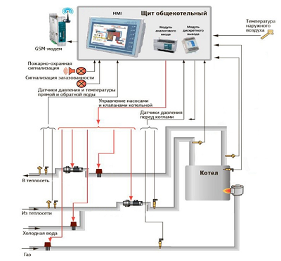
Figure 1.1 – Functional diagram of the automatic heating control system.
1.2 Composition and operation of the system
The analysis of technology, which is implemented on the basis of smart house
control system can be identified:
- Control over the Internet.
For control and configuration of the home office, car, etc. System program
smart home
allows you to use e-mail to transmit the necessary commands. For this purpose, the main program is divided into two separate modules, one of which is in the house and wait for instructions. The other is located on the user's computer. - Remote control.
For the convenience of household devices in the home, it was founded remote control that allows you to combine the management of TV, VCR, stereo, satellite receiver. It also allows you to enable or disable: lighting, electrical outlets controlled, different lighting scenarios. With the combination of a few buttons – to open the gate, put the house for protection and make a lot of other different activities
- Control your computer.
Friendly user program running in the Windows operating system, allows you to enable or disable specific modes of the system
smart house
, as well as make adjustments of its work, read and print communications protocol.An important element of the system is the central control unit. The computer provides the versatility, flexibility, scalability, ease-of-use. Using a computer, you can solve a great number of very different tasks in the same system.
- Management of the tablet.
Most systems Smart home runs in automatic mode and does not require any human intervention. However, there is always the information that should be reported to the user, or that it would, in principle, be useful: the outdoor temperature, weather forecast, images from surveillance cameras, records of the automatic algorithms and so on. Furthermore, in some cases it is necessary to be able to remotely control certain elements, such as light, household appliances, to make changes in climate work and security modules.
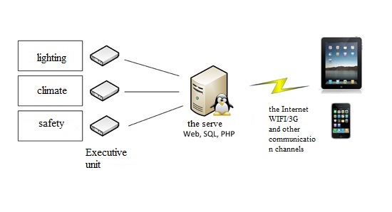
Figure 1.2 – Management plan using the tablet.
Thus, the Smart House is a schematic as if of three main elements: a central processing unit, controlled by their actuators and interface device, with which you can communicate with the CPU.
The central processing unit – a server. As a server, you can use anything from a supercomputer with helium cooling to the router and the microcontroller.
- Management of industrial logic controller (PLC).
As with any automated system, the system of
smart house
is built on the three-level principle: the lower level (temperature sensors, contactors and relays), to the average level using a programmable logic controller, input-output modules, the GSM-modem. The upper level (HMI, SCADA) includes an operator panel and server computer on which the implemented web-based interface.An important stage in the development of
smart house
control system is an analysis of the building life-support systems as a control object, ie identify all material input, output and disturbing variables.
2 Synthesis of automatic control system
2.1 Selecting the type of development and the structural scheme SAU
In developed ACS will use the principle of management with feedback. The control circuit with feedback is most prevalent in practice. The control system monitors the observable parameters (variables) and on their basis creates a control algorithm.[5]
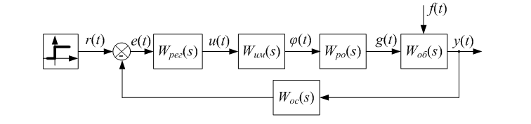
Figure 2.1 – Block diagram of the control for the deviation.
Monitoring and information about the real values of the heating performance of the process are carried out with the help of feedback.
Control deviation e (t) is the difference between the actual measured value and its preset value. Under the control unit refers to a technical device, through which the automatic control of the control object.
Controlled variable y (t) is determined by the setpoint r (t) at the input of the system, ie, exposure introduced into the system and determining the necessary law changes the controlled variable. On the input of the system in comparison, an element other than the master effects fed the actual value of the controlled variable by the feedback loop. At the output of the comparison element, at the input of the control device, there is a deviation or control action that provides the controlled variable change on a given law.
The control systems of feedback can be defined as information communication, by means of which the control portion is supplied to the control implications of the information objects, information about the new state of the object, which appeared under the influence of the control actions.
Fig. 2.2 is a block diagram of ACS thermal model home.
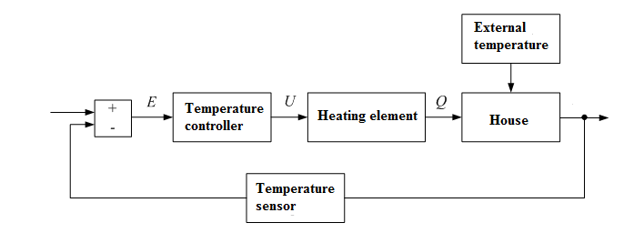
Figure 2.2 – Lock diagram of ACS thermal model home.
The room temperature is measured by a temperature sensor, the value is compared to the set by the user. The error signal is supplied to a temperature controller, which controls the heating element. The heat flux supplied from the heating element in the heating system of the house, which leads to an increase (decrease) in temperature in the room of the house.
2.2 Synthesis and Simulation SAU
Since the heating system is designed so that the heating element can only operate in two modes:
• is on, maximum power;
• is off, the minimum (zero) power.
As a law regulating the room temperature will choose the two-position controller. It provides good quality of regulation for the inertia of objects with a small delay, do not require adjustment and easy to operate.
Block diagram of a two-stage control system is shown in Fig. 2.3.
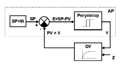
Figure 2.3 – Block diagram of a two-stage control system.
Fig. 2.4 introduced the notation: AR – two-position controller; DU – management facility; SP – control point E – mismatch control; PV = X – controlled variable; V – control action; Z – disturbance.
To prevent the bounce
of the control of the output device and the heating element near the job SP (too frequent switching on the heater),
provides hysteresis H.
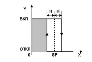
Figure 2.4 – Static characteristics of a two-stage control system.
Job description bi temperature control system in a room with a heater, may be represented as follows:
• The heater is turned on until the room temperature (X = PV) reaches a predetermined point value SP + H, Y Output Controller (heater) is disabled if the controlled variable (temperature) above the set point SP + H;
• Reintroduction of the heater takes place after reducing the temperature to a value of SP-H, ie, H hysteresis given switching element.
On the basis of mathematical relations construct the automatic temperature control circuit in a country house in Matlab & Simulink.[1]
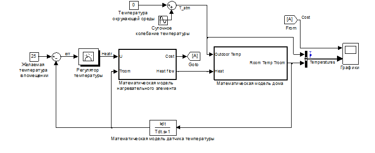
Figure 2.5 – Block diagram of the automatic control system in Matlab & Simulink.
We investigate the behavior of the system when developing tasks and perturbation signal. Set temperature to be maintained in the room – 25 degrees Celsius by default.
The temperature of the environment as a model the average air temperature in the street and daily fluctuations of the outside ambient temperature.
in the Charts
section After running the simulation process is visualization.
Graph 2.7 and 2.8 shows the transient temperature changes of walls, windows and roof of the house, as well as heat loss through them for two days. graphs analysis suggests that most heat loss occurs in the building through the ceiling and walls. Therefore, to reduce the payment for heating is necessary to take these measures on warming the structural elements of the house.
Figure 2.9 – Transition process air temperature in the house.
The controller is configured in such a way that if the room temperature falls to 23 degrees, then turned on the heater and raises the temperature to 27 degrees. After that, the heating element is switched off.
external temperature varies sinusoidally while the room temperature is maintained within ±2 degrees Celsius relative to the setpoint. Graph 2.10, you can see how the changes in heating energy costs. They increase when the heating system starts to heat the room.

Animation - the simulation Results of the ACS.(5 frames, 120 KB)

Animation – the simulation Results of the ACS.(5 frames, 120 KB).
Conclusions
It was found that the category of typical subsystems within the LSS usually related engineering systems available in every building, regardless of its classification: ventilation, power supply, heating, water supply, lighting, gas supply, CCTV system and fire alarm.
Analysis of existing technologies such as the construction of smart home
systems showed that promising is the realization of life-support
systems of buildings management is not only based on the controller, but with the addition of a personal computer or tablet. Because the
smart home
can manage not only the communication, climate and equipment, but also the medium for data exchange and transformation,
media server, content server, and if Web-based computer-based system is a promising and interesting solution.
The basic variables affecting the maintenance of life support systems of the building parameters.
Under the structural scheme of automatic control system of temperature conditions in the room. A mathematical model of the control object and the whole of ACS. The simulation model of the system is assembled in the annex Simscape Matlab & Simulink package.
As a control relay control law is selected. After analyzing the graphs can be concluded that the developed system is stable and transient quality indicators meet the requirements of the customer.
References
- Чен К. MATLAB в математических исследованиях [пер. с англ.] / Чен К., Джиблин П., Ирвинг А. – М.: Мир, 2001. – 346 С.
- Шугаев С. Система
умный дом
/ С. Шугаев // Автоматизация технологических процессов. – 2013. – №2(13). – С. 15–17. - Шишкин С.
Умный
дом на программируемых логических / С. Шишкин // CONTROL ENGINEERING РОССИЯ. – 2014. – №6(54). C. 25–29. - Гололобов В. Н. «Умный дом» своими руками / В. Н. Гололобов. – Москва: НТ Пресс, 2007. – 416 С.
- Чернышев Н. Н. Использование беспроводных технологий при построении современных информационно-управляющих систем / Н. Н. Чернышев, И. А. Гарматенко // Научно-технический сборник
Труды Северо-Кавказского филиала Московского технического университета связи и информатики
, часть I. – Ростов-на-Дону.: ПЦУниверситет
СКФ МТУСИ, 2014. – C. 45–48. - Марк Э. С. Практические советы и решения по созданию «Умного дома» / Э. С. Марк. – Москва: НТ Пресс, 2007. – 421 С.
- Cистема Умный Дом – технология экономии, удобства и комфорта высокого уровня [Электронный ресурс].