
Abstract
Content
- Introduction
- 1 Relevance of the topic
- 2 Aims and objectives of the study
- 3 Analysis of the Automation object
- 4 Designing of Automatic Control Systems
- 5 Software
- Сonclusion
- List of references
Introduction
Every day automation plays an increasingly important role in industrial activity and the life of human society, to satisfy its growing needs. In recent years, due to a marked decrease in natural resources at an alarming global climate change and the growth of the Earth's population automation role more and more intensified, and the scope of its application is continuously expanding.
There is no technical processes today that manage without automation - from simple systems used in everyday life, to the most complex industrial production processes [3, 5]. It is impossible to imagine a comfortable and safe everyday life without many technical devices which became such because of automatic used in them.
1 Relevance
To date, the question of stabilization of unstable physical objects is one of the most frequent problems of control theory faced by engineers in this area. Therefore, there is a need for a rich experience in solving similar problems for future engineers. It is important to obtain not only theoretical knowledge and skills in working with mathematical models, but primarily practical skills and experience with real physical objects, the physical nature of which can not be fully described by a model [4].
In parallel with this technical progress is moving towards miniaturization of sensors, actuators, reducing their energy consumption, cost, and improve flexibility, reliability and speed of chips and microprocessors. This creates the possibility of creating objects that combine all the hardware is not only for the formation of the control action, but also for the measurement of physical quantities feedback and implementing complex control systems. Ability to fully implement all of these functions in the middle of a single object allows it to be self-contained and compact.
This factor is pushing engineers to create more and more mechanically simple, but still more complex objects control method. This in turn requires the creation of demonstration models that help in understanding and learning ways to stabilize physically unstable objects, hone practical skills in designing systems of indirect measurement of physical quantities.
Tools and solutions of automatic control are constantly being improved, so the demonstration model should move with the times, to give a true picture of the current status of the various objects of automatic control problems.
2 The goal and objectives of the work
The goal – creation of the laboratory setup for studying ways to stabilize physically unstable objects, gain practical skills for the design of control systems with the use of smart sensors.
The purpose – to develop the hardware platform in the form of an inverted pendulum, the development of algorithms for determining the tilt angle, balance, movement and connection to a PC and the remote device.
The main objectives of the work:
- Analysis of existing systems of stabilization and dynamic balance.
- Development of a mathematical model of the object.
- Development of functional and structural schemes of the object.
- Modeling of dynamic processes in the object.
- Analysis of existing methods for determining the tilt angle and processing of readings from the sensors.
- Synthesis of algorithms of identification balancing robot parameters (parameters of the engine, tilt, position in space).
- Design of the automatic control system, followed by the selection of components.
- Creation of software for the remote control.
- Development of bench model of balancing robot.
3 Analysis of the Automation object
Classical mobile platform, which have almost all cars and trucks, has four wheels. This provides a platform balance and stability when driving, but this design has several disadvantages:
• a large number of wheels increases platform dimensions and number of moving parts, which reduces reliability;
• failure to install a separate motor for each wheel;
• location of the wheels at the corners of the platform leads to a need to establish a subsidiary nodes to transmit forces from the engine to the wheels (differential) and for maneuvering (steering lever), which complicates the structure and platform management.
These deficiencies deprived platform with an inverted pendulum design. This type of platform is as follows: on a single axle situated only two-wheel drive, while the weight of the platform is centered on the axis of the wheel (fig. 3.1.).
Having only two wheels reduces the size and increases the reliability and the separate control of each of them (with the help of two engines) makes the platform very maneuverable. It can move while maintaining balance and is able to perform a U-turn on the spot.
A significant drawback is that such a platform is not stable – if the engine is switched off, the platform will certainly fall, because the center of mass of the platform is very high. This disadvantage can be compensated by automatically support balance. It is possible to produce control actions to DC motors with special regulation law, which, in turn, will keep the platform in equilibrium, but it needs to measure the deflection angle of the platform surface normal.
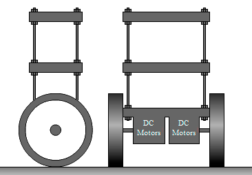
Figure 3.1 – Platform in the inverted pendulum form
The idea of maintaining balance is quite simple, because the construction has a single point of equilibrium where the cargo mass center is located directly above the axis of rotation [1]. If the center of gravity design deviates to one side, then the force of gravity is partially transmits through the resistance to the ground, and the other component of its design creates a moment of rotation, which tends to fill up the construction on the side. To compensate this effect, the system should move with acceleration in the direction of incidence. The force F, which creates acceleration, converts the force acting in the direction of support, and the force that creates reverse torque of the construction (fig. 3.2).
It is necessary to satisfy next condition to maintain the balance:
But if we consider only small deviations from the equilibrium state ( α→0 ), thanks to linearization we can get a simple condition for equilibrium:
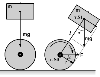
Figure 3.2 – Functional diagram of balancing
Legends:
M – mass of the wheelbase;
m – mass of load;
α – tilt angle from the normal to the surface;
p. S0 – center of mass of the wheel axle;
p. S1 – center of mass of the load;
l – distance between points S0 and S1;
g – acceleration of gravity;
r – radius of the wheel.
The provision of a constant acceleration in a real system is a very difficult task and that is why in order to maintain the balance of the system we should not only compensate for the force, which fills up the structure, but also gradually restore the vertical, that is:
Conditional maintain equilibrium principle can be illustrated by the following animation.
Figure 3.3 – The principle of stabilizing the object (animation consists of 22 frames with a delay of 100 ms between them, the number of animation cycles is 7)
4 Designing of Automatic Control Systems
Generalized block diagram of ACS of balancing robot provided on the figure below [2, 7, 8].
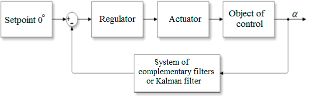
Figure 4.1 – The overall structural diagram of the control system
Control object is an inverted pendulum design (mobile platform). The role of the actuator performed by two DC motors. For motor control, the motor driver system is required. Tasks management and control computation performs microcontroller, a control law implemented by software.
The output of the system is the angle of deviation from the normal to the surface, measured using microelectromechanical systems (MEMS motion sensors), which represent the union of an accelerometer and a gyroscope. The purpose of the system is to keep the tilt angle is zero or close to zero. Functional diagram is shown on fig. 4.2
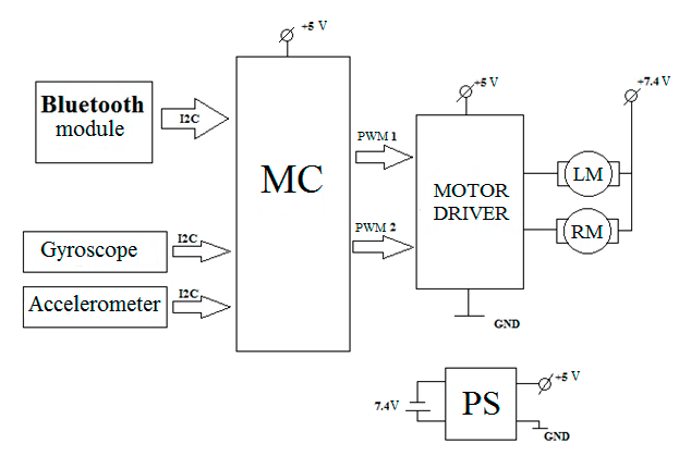
Figure 4.2 – Functional diagram of the control system
It is important to mention about the choice of the microcontroller. To date, the market represents a very wide range of different smart devices that are engaged in calculations in real time. Very popular among the consumers is an 8-bit microcontroller Atmel's AVR. They are often used for various tasks in robotics.
However, technological progress is moving very quickly, and 8-bit microcontrollers, despite the simplicity of their use, gradually giving way to more productive families which are able to perform more operations per second and have more built-in interfaces, internal modules, and even easier to prototyping than a conventional 8-bit microcontroller AVR, such as, for example, ATMega8.
That is why it was decided to use as a computer assembly mbed NXP LPC1768 microcontroller. This single-board microcontroller has on board all the necessary software.
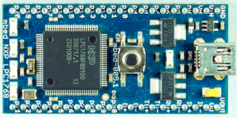
Figure 4.3 – Microcontroller mbed NXP LPC1768
This card is designed for the rapid design of various electronic devices and robots. Performance of the microcontroller is about 100 MIPS. LPC1768 microcontroller has an ARM Cortex-M3 core. It can function and do the computation at a frequency of 100 MHz.
The main characteristics of the microcontroller mbed NXP LPC1768 are:
- high-performance ARM Cortex-M3 core;
- functioning at the frequency of 96 MHz;
- 32 KB of RAM, 512KB FLASH-memory;
- interfaces: Ethernet, USB, 2xSPI, 2xI2C, 3xUART, CAN;
- 6 channels that can supply a PWM signal;
- 6 ADC channels, 6 channels DAC;
- 40-pin DIP form-factor 54x26mm sizes;
- powered by USB or from an external source 4.5-9V;
- online-compiler and development environment;
- built-in drag 'n' drop Flash-programmer;
- 3.3V stabilized output voltage;
- complete software and technical support, numerous examples of programs.
Wiring of the controller is shown below.
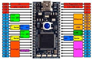
Figure 4.4 – Controller's wiring scheme
Due to a mbed hardware platform and a rich set of software components (ready libraries, program codes for various tasks, the online development environment with all necessary functions) it is possible to quickly create software for the control system.
5 Software
The main program's algorithm represented in the flowchart below (fig. 5.1). After powering on, all elements of the ACS are initialized (motors, Bluetooth module, sensor). Thereafter, the control coefficients from the PID file are read out and the angle information from the gyroscope and accelerometer is read out too. Next comes the test – “Does the deviation from the normal is too great?”. If less than 150 degrees or more than 200 degrees, it means that the robot is falling and the controller turns off and restart the engines. Otherwise, there is a test – “Does the data coming via Bluetooth?”. If yes – this data becomes the control actions for the further movement of the robot. Otherwise, the impact generated by the angle of deviation from the normal in order to stabilize the structure becomes the control actions. Thereafter, the robot starts moving in accordance with the control action of controller and recalculates PID values.
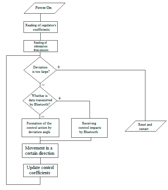
Figure 5.1 – Block diagram of the main program
For remote control, it was decided to create an app on the Android operating system that uses Bluetooth for connectivity and data transfer between the device and ACS of balancing robot. Its interface is shown on fig. 5.2.
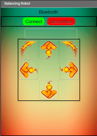
Figure 5.2 – Graphic interface of the remote control application
When you press the Connect button, you can select a device to connect from drop-down list. The control action is transmitted through the control arrows. It is possible to move forward / backward, turn clockwise and counter-clockwise (engines work in different ways), turn left and right (one of the engine is not running).
Сonclusion
In this work carried out research of methods and algorithms for the identification of balancing robot parameters [6]. In the first phase, automation object was analyzed. The most popular solutions to the problem of stabilization, handling, identification and determination of the angle of the objects in the form of an inverted pendulum were considered.
Next, the hardware components of the system were selected and developed management concept of the object. In the last section, software of the balancing robot were completely worked out.
This work is the basis for creating a bench model of the robot.
This master's work is not completed yet. Final completion: June 2017. The full text of the work and materials on the topic can be obtained from the author or his scientific adviser after this date.
List of references
- Капица П. Л. Динамическая устойчивость маятника при колеблющейся точке подвеса. Журнал экспериментальной и теоретической физики, т. 21, вып. 5, 1951. – с. 588–597.
- Певзнер Л. Д. Теория систем управления. – М.: Издательство МГТУ, 2002. – 469 с.
- Москаленко В. В. Электрический привод: Учеб. Пособие для студентов учреждений сред. проф. Образования. – М.: Мастерство; Высшая школа, 2001. – 368 с.
- Аничкин И. М. Применение нейронной сети для управления мотоциклом.
- Брандина Е. П. Электрические машины – СПб.: СЗТУ, 2004. – 152 с.
- Симою М. Определение коэффициентов передаточных функций линеаризованных звеньев систем регулирования. Автоматика и телемеханика, 1957. – 514–527 c.
- Льюнг Л. Идентификация систем. Теория для пользователя: М.: Наука, 1991. – 432 с.
- Дорф Р. Современные системы управления / Дорф Р., Бишоп Р; Пер. с англ. Копылова Б.И. – М.: Лаборатория Базовых Знаний, 2004. – 832 с.
