
Abstract
Content
- Introduction
- 1. Relevance of the topic
- 2. The purpose and objectives of the study, expected results
- 3. Development of the device
- Conclusion
- References
Introduction
In the mid-20th century, technological progress has made a leap in the development of computer technology. Then computer technology began to grow exponentially. Intuitively, this fact describes Moore's Law [1]. By the mid-20th century science fiction emerged a large number of works describing is not computers, and robotics: robotics formed laws [2], the alleged appearance and capabilities, surpassing human. In the wake of technical progress and computer technology emerged robotics. At the moment, we can observe an increasing introduction of robotic devices in the world around us, and in no distant beduyuschem perhaps we will see just robots that live with us side by side and helps us to improve our lives. But to make robots fit into our lives need to be equipped with systems of orientation in space.
1. Relevance of the topic
The interaction with robotic technology surrounding objects there is a need for systems orientation in space. As these systems are needed in those cases where the operator any moving machine or device cannot reliably assess the managed object moving in the space and its interaction with other objects. With the development of scientific and technological progress, this problem is becoming more urgent. Orientation in space systems increasingly permeate our daily lives, from mobile phones (proximity sensors, GPS, accelerometer, and more) to the car (GPS, parking sensors and so on.). The introduction of these systems in the aerospace industry is an integral part of progress in this area. Consequently, research and development of systems of orientation in space is important.
2. The purpose and objectives of the study, expected results
The aim is to research and development of robotics systems, orientation in space.
It is necessary to develop a system that provides autonomous robot with the necessary information for its movement in space. This system should be designed taking into account the following requirements:
1) The minimum cost;
2) Easy to assemble;
3) Easily incorporated into robotic devices;
4) Versatile for different types of robots.
Another task is to develop a system that will provide the operator to control the robot in case of a situation where the robot cannot cope with the task, or there was an emergency situation.
3. Development of the device
Development of the device can be divided into two parts: hardware and software.
The hardware part
Development of the system of orientation in space is made on ArduinoUno platform (pic. 1). Arduino Uno controller is built on the ATmega328 [9]. The platform has 14 digital inputs / outputs (six of which can be used as PWM outputs), six analog inputs, a 16 MHz crystal oscillator, USB connector, a power connector, the ICSP connector and the reset button. To use the platform you need to connect to a computer via a USB cable or supply power using the AC / DC adapter or battery [10].
The platform is programmed by Arduino software. Arduino programming language devices based on C/C++ [11].
For programming the microcontroller used IDE Arduino 1.0.5. ATmega328 microcontroller comes with a built-in loader, facilitating entry of new programs without the need for external programmers. The device operates autonomously –without the intervention of the operating system or the user, the power unit from the stand-alone battery.
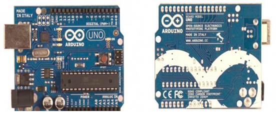
Picture 1 – Appearance ArduinoUno
To measure the distance to the object will use an ultrasonic distance measuring sensor HC-SR04 [12]. Rangefinder sensor works on the principle of sonar, but rather – sends the ultrasonic beam and the delay of the reflected signal from the object determines the distance to the target (pic. 2). As the basis for operation of the device using ultrasound, sonar is ill-suited for the determination of the distance to the sound-absorbing objects. The surface of the object must be flat and smooth for a perfect measurement of the distance.
Picture 2 – The principle of operation of ultrasonic range finder HC-SR04
(animation: 6 shots, 6 cycles of repetition, 140 kilobytes)
To determine the robot position in space will use the module GY-531 [13]. MPU6050 chip comprises an accelerometer, a gyroscope, and a temperature sensor. MPU6050 is the main element of GY-531 module (pic. 3). Apart from this chip on-board unit is required strapping MPU6050, including pull-up resistors I2C interface, as well as a voltage stabilizer by 3.3 volt Low Dropout (when powered at 3.3 volts at the output of the stabilizer will be 3 volts) with filter capacitors . The board has SMD LED with a limiting resistor, performing the function of supply voltage indication. Sensors Gyroscope and accelerometer fabricated as MEMS (micro electromechanical system) - external influence on the sensor first changes the state of the mechanical part, and then change the status of the mechanical part leads to a change in electrical signal. In a word, in one case it collected not only electronics, but also the mechanics. In MPU6050 chip contains just two MEMS sensor, the manufacturer claims that their mutual influence on each other is minimized.
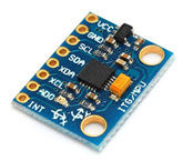
Picture 3 – Appearance GY-531
The system, developed on the GY-531 module framework should define the angle of ascent or descent of the moving object and depending on it to generate control signals to increase / decrease the voltage supplied to the engines. If the object overcomes the rise, the system determines the lifting angle and increases the voltage applied to the motor so as not to lose speed. If the object overcomes the descent, the system determines the angle of descent and reduces stress on the engines to prevent an uncontrolled acceleration of the object.
It should be noted that the draft accelerometer and gyroscope used simultaneously to improve the accuracy of the data. This is due to the specifics of different accelerometer and gyroscope, as well as parameters defined by them.
Next, you need to develop a system for controlling the motor. In this system, the engine will run the same platform using the engine driver IC L293D. Engine Driver – It is a device that converts the control signals into low power current, sufficient to control the motors. L293D contains just two drivers to control a small capacity motor (four independent channels, combined in two pairs). It has two pairs of inputs for the control signals and two pairs of outputs for connecting electric motors. In addition, the L293D has two inputs for switching each of the drivers. These inputs are used to control the speed of rotation of electric motor using PWM.
L293D provides for the division of power chips and managed by the engine, allowing you to connect electric motors with more voltage than that of the chip. Separating power circuits and motors may also be necessary to reduce the interference caused by voltage spikes associated with the motors work. The engine management system (pic. 4).
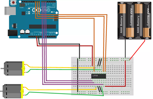
Picture 5 – Motor control circuit
The software part
The software part is implemented in the code for the microcontroller firmware (Arduino sketch). The program should determine the distance to obstacles and calculate the robot position in space to generate control signals, by means of which will be a robot motor control.
It should be noted that the draft accelerometer and gyroscope used simultaneously to improve the accuracy of the data. This is due to the specifics of different accelerometer and gyroscope, as well as parameters defined by them.
Gyro gives instant value of the angular velocity with a resolution specified in the settings. If the flash microcontroller and look at the resulting data, we can see only zeros. If you start to turn the sensor, we obtain the instantaneous values instant the angular velocity. We obtain the velocity in degrees per second, which means that the linear speed have no effect on these indications – readings will change only when you turn the sensor in space. Then, using these data can be obtained in the orientation of the object space. It needs to obtain the instantaneous value of the angular velocity and multiply it by the time interval between polls of the gyroscope sensor. Example Resolution 2000 degrees per second, the interval between polls sensor 0.1 seconds, the value of the instantaneous velocity of 300, then 300 * 0.1 = 30 – During this time the gyro axis is rotated by 30 degrees. Further, each value obtained need to add to the previous. If the axis moved in one direction - the value of 30 degrees when in the other, -30, so when the sensor is returned to its original position is always (ideally) is 0, the deviation from the reference position, when performing the above steps, we obtain the angle of deviation . Processing gyro angles of the three axes of the orientation of the object can be obtained in space.
Thus, by integrating state of the position angle, and also integrates the error – long-term use can be obtained is absolutely wrong values. Therefore gyro often used in tandem with the accelerometer forming a simple embodiment, the alpha-beta filter or a complementary filter.
The accelerometer detects acceleration in three axes. As a result, data can be obtained by transforming them with a geometry which can also be the orientation of the object in space. In addition, the accelerometer measures linear acceleration, that is, the orientation of the object may be distorted when the sensor is moving in a linear direction. Also, using the accelerometer can detect movement of an object or a collision. For example, to detect the fall of an object or a push on the obstacle to get it.
The data from the accelerometer get always accurate enough, that is, zero is always zero under any influences (meaning depends neither on time nor on the nature of the impact), but the disadvantage lies in the fact that the data are from the noise in a certain data range, It has to tenths of a degree to accurately measure the angle will not work. But on the basis of experimental data, the accuracy to the nearest whole degree values kept quite stable. Do not forget also about the influence of linear acceleration.
Conclusion
Thus, during the development of system orientation in space identified advantages and disadvantages of ultrasonic sensors. A determination of the distance to the object system and designed a robot that is in constant motion, change the direction you approach an obstacle, and confirms the accuracy of the developed system of orientation.
Completed development and modeling of the electronic device, which determines the position of an object in space by means of an accelerometer and a gyroscope. The device determines the angle of descent or climb, and generates control signals for the adjustment of the engines. The resulting system of orientation in space, easy to use and cheap in the assembly. Changing motor driver chip can be controlled given any electric power system.
To program the microcontroller using C language development environment translates the program in language Assembler – understandable for the microcontroller.
Список источников
- Wikipedia – the free encyclopedia, the article “Moore's Law”. [Electronic resource]. – Access mode: ru.wikipedia.org
- Wikipedia – the free encyclopedia, the article “Three Laws of Robotics”. [Electronic resource]. – Access mode: ru.wikipedia.org
- Edward Red. “Robotics Overview”. [Electronic resource]. – Access mode: eaal.groups.et.byu.net
- Samuel Bouchard. “7 Types of Industrial Robot Sensors”. [Electronic resource]. – Access mode: blog.robotiq.com
- Андрей Антонов. Описание движения мобильного робота. [Electronic resource]. – Access mode: robotosha.ru
- Популярная робототехника – «Сенсор». [Electronic resource]. – Access mode: poprobot.ru
- Информационный сайт по разработке роботов Home roboticlab «Инфракрасный датчик расстояния». [Electronic resource]. – Access mode: home.roboticlab.eu/ru
- Диденко Г.С. Роботизированная система с визуальным наблюдением/ Г.С. Диденко, В.А. Краснокутский// Материалы Международной научно-техническая конференции студентов, аспирантов и молодых ученых «Информационные управляющие системы и компьютерный мониторинг 2014», Донецк.
- Официальный сайт Ардуино в России. [Electronic resource]. – Access mode: arduino.ru
- The official website for Arduino. [Electronic resource]. – Access mode: arduino.cc
- Подбельский В. В. Программирование на языке Си: Учеб. пособие. – 2-е доп. изд./ В. В. Подбельский, С. С. Фомин. – М.: Финансы и статистика, 2004. – 600 с., ил.
- Горин Н.А. Разработка системы ориентирования в пространстве с использованием ультразвукового датчика/ Н.А. Горин, В.Н. Струнилин// Материалы Международной научно-техническая конференции студентов, аспирантов и молодых ученых «Информационные управляющие системы и компьютерный мониторинг 2015», Донецк.
- Горин Н.А. Разработка системы ориентирования в пространстве с использованием модуля GY-531/ Н.А. Горин, В.Н. Струнилин// Материалы Международной научно-техническая конференции студентов, аспирантов и молодых ученых «Информатика, управляющие системы, математическое и компьютерное моделирование 2016», Донецк.