System programming
Abstract
The contents
A computer technology growth is intense pace. The scope of their application is expands and a need of improvement and development is increases. One such area is the computer graphics. Computer graphics has started its development in the 50-ies of the last century. Since then, its importance is increasing year by year. New technologies and algorithms are developed. Currently there are many imaging techniques to achieve different effects, depending on the task.
1. Hardware and software support for ray-tracing
Ray-tracing allows obtaining the images with high realism. It easily realizes many kinds of effects such as reflections, transparency, shading, and many others. And also this method allows tracking beams which expands its application not only for simple imaging, but also for various processes modeling.
The aim is a reduction of hardware costs for beam forming and finding their intersections with the scene objects in the implementation of the reverse ray-tracing algorithm. To achieve the aim the following tasks are necessary to solve:
Subject of research – the synthesis of images based on the ray-tracing method.
Object of research – hardware solutions for ray-tracing realizations.
The scientific significance of the work lies in the further development of the theory and practice of graphics synthesis systems developing and their use for the improvement of algorithmic and architectural solutions aimed at functioning in real time.
So, what is ray-tracing? Ray-tracing – a tract tracing process from a given point in the scene and assess the impact of the material on this point other points of the three-dimensional environment. The result is a modified color of the analyzed point. Thus it is possible to calculate the shadows, reflection and direct illumination of the object [1].
With the direct ray-tracing (radiosity) from the light source (1) leaves a light beam. They tracked the trajectory and in contact with the object (2). Further trajectory is tracked from that point toward the viewer (4), then obtain the pixel value (stage 3) (Figure 1).
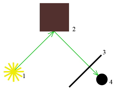
Figure 1 – Example of pixel values radiosity methods
Radiosity method is based on the assumption of diffuse reflection of light, which allows advance, at the stage of preprocessing, calculate the energy parameters of the surfaces of the objects displayed, and thereby eliminate the step of calculating the illumination parameters of the working stage and combine the steps of geometric transformations, separation/screening and removal of hidden elements. As a result, system solutions form the values of the energy flux density for each site listed in the sections of the intensity, the value of which does not depend on the observer's position. To construct the image intensity values are translated into the faces of approximation nodes areas, and at the stage of drawing is performed, linear or bilinear interpolation of the intensities of the beam closest to the point of intersection of sight with the face nodes. Radiosity method consists of four processing steps:
In this case the first three steps can be performed in preprocessing step and only the last one – on the working stage.
This method has a serious drawback: a lot of unnecessary calculations. From the light source to the object reaches only a part of rays. At the same time spent on the calculation of rays that eventually reach the objects and will not play a role for the visualization of a certain scene. Therefore, there is a method of reverse ray-tracing.
When we use reverse ray-tracing we trace rays that enter the eye of the observer. From eyes emitted rays. When crossing the beam so the scene is tracked object: seen whether this point is one of the light sources (if they more than one). For this purpose from this point of rays emitted by each light source. If the beam is crossing with another object before it reaches the source, then such a point is in the shadow and highlight it is not necessary. If the beam has reached source, the illumination of the point of Buda is the sum of the illuminations from each such source. If the object has reflective properties, and yet, it repeats a similar trace to the reflected beam. This method automatically reduces the computational load.
3. The meaning of the hardware support
To implement ray-tracing algorithm in real time requires a hardware support is necessary to apply. An image visualization has to perform a large number of calculations. This number can be reduced if it is taken equal to the adjacent pixels. For this purpose, the interpolation method was proposed. For example, if a 1024×1024 image interpolate for 4×4 blocks, the number of processes is reduced by 7 times [2].
Despite various modifications of the algorithm the number of calculations for high-quality visualization is poor. But at the same time, this algorithm has a high ability to parallelization. This ability is limited only by the technical capabilities of modern graphics cards and systems. Therefore, for ordinary users ray tracing is only available in part. Graphics systems using this method are costly. Therefore, they can afford to use only the large companies that are professionally involved in computer graphics or research using simulation.
Consider the example of parallelization of the algorithm on an example of a mathematical expression for the ray intersection search polygonal object. To define a Ray a parametric equation (1) is used. Each face (plane) of the object can be defined by the use of vertices coordinates {x [n], y [n], z [n]} and the normal vector N = {nx, ny, nz}, are represented in the object coordinate system (OCS).

where  – the base-point of Ray in the OCS;
 – the parameters of the vector in the OCS.
Parameter t fot polygonal model has to be calculated as relation of dividend (dev) to devisor (div) (2).
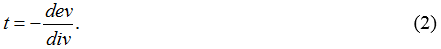
Devisor - scalar product of viewpoint vector to normal vector of a plane(3).

To calculate parameter d for a plane equation(4). To calculate dividend(5).
UML allows to create a platform for independent description, which can then be used to make decisions about the software (firmware) or hardware implementation of one or another part of the system. UML is supported by a large part of the tool [3]. To construct UML-diagrams distinguish elementary performing blocks (Figure 2).
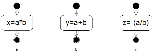
Figure 2 – UML representation of the elementary performing blocks (EBL): a) Sub-machine M1, b) Sub-machine A1, с) Sub-machine B1
The implementation of the expression (3) requires 3 multiplications and 2 additions (Figure 3), this block is called P0BL. Using elementary performing blocks introduced above we get the UML-diagram block calculation of the scalar product.
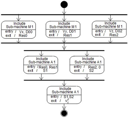
Figure 3 – UML-diagram of the scalar product calculation block (P0BL)
Block calculation of the numerator is the same organization, but in Sub-machine A1 with Res2 need to apply the value of d. Let a block P1BL. The dividend and the divisor are independent and, therefore, can be calculated in parallel. At the same numerator, you must first calculate the parameter d. Figure 4 shows a sequence of computations.
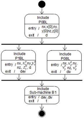
Figure 4 – UML-diagram sequential-parallel implementation of the expressions (3)–(5)
When calculating dev instead block P1BL structure apply block with P0BL structure, and then the result (dev0) add parameter d (expression 6), the expression (3), (4) and the first part (6) can be calculated in parallel (Figure 5).

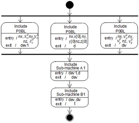
Figure 5 – UML-diagram of a parallel implementation of the expressions (3)–(5)
This way you can visually assess the implementation of the different ways and choose the best solution to the problem.
4. Analysis of the current state of the method’s applications
Due to the fact that using ray tracing method achieved very realistic images, the interest in this method is quite high. It is used for computer graphics in cartoons and movies. This company, like PIXAR has long worked with NVIDIA and creates a new animation in less time and with quality graphics (Figure 6).
Figure 6 – Using the NVIDIA OptiX and Katana in real time (PIXAR) (animation: 306×146px, 5 frames, 10 cycles, 146kb)
NVIDIA is actively working on various technologies (CUDA, Iray) and GPUs (GeForce, Quadro and Tesla) to speed up the calculations by ray tracing.
Imagination Technologies has demonstrated the performance of their hardware acceleration of ray-tracing. Specialized accelerators Caustic 2500 (RT2 with two chips and 16 Gbytes of DDR2 memory) and Caustic 2100 (RT2 one chip and 8GB of DDR2 memory) (Figure 7) were presented in January 2013 [4].
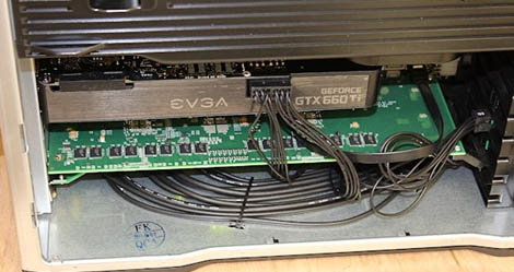
Figure 7 – Card with accelerator beams trace Caustic 2500, placed under the video card
More in 2014, Imagination Technologies introduced PowerVR GR6500, who became the first mobile GPU, the block containing the selected Ray Tracing Unit (RTU), which is responsible precisely for the formation of images using ray tracing. However, this technology is still not reached the consumer segment, although professional desktop accelerators sold quite a long time [5]. At the Mobile World Congress2016 the company introduced a series of GPUs for the budget segment with the new GPU-architecture – Series8XE (Figure 8). It will be used in smartphones, tablets, TVs, cars and streaming [6].
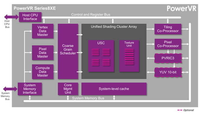
Figure 8 – Imagination Technologies Series8XE
Not far behind them and AMD. In 2016 the company opened the source code of the library of three-dimensional imaging ray tracing method FireRays 2.0 and the publication of its source code. The library can use different backends (OpenCL GPU, OpenCL CPU, Embree and soon Vulkan) to speed up the calculation of the interaction of rays with surfaces and supports the work of Linux, OS X and Windows. Besides video cards AMD FirePro (graphics card for workstations) and Radeon (graphics card for desktop PCs and laptops), hardware acceleration is also provided for the GPU Intel (HD 4300, HD 5300) and NVIDIA (GeForce GTX970 and Titan X). Open code under the MIT license and placed under the patronage of the project GPUOpen [7].
In turn, the development INTEL exist without the use of GPU. OSPRay is an open source, scalable, and portable ray tracing engine for high-performance, high-fidelity visualization on Intel Architecture CPUs. OSPRay is completely CPU-based, and runs on anything from laptops, to workstations, to compute nodes in HPC systems. OSPRay internally builds on top of Embree and ISPC (Intel SPMD Program Compiler), and fully utilizes modern instruction sets like Intel® SSE, AVX, AVX2, and AVX-512 to achieve high rendering performance [8]. Embree is a collection of high-performance ray-tracing kernels, developed at Intel [9].
An example of non-traditional use of NVIDIA technology to solve the problem that arose with the erection of the tower in London. But the same curved glass that gives the 37-story tower the nickname “The Walkie Talkie,” also has a knack for concentrating sunlight. The result: a hot spot that melted part of a nearby Jaguar XJ and cooked shampoo in a local barber shop. Thanks to a new generation of glass-sheathed buildings with radical computer-designed curves. Those curves reflect – and concentrate – light in ways that have been hard for designers and engineers to predict. Until now. Such powerful simulations build on technology we first demonstrated at last year’s GTC. They showed, together with Honda, the first interactive visualization of an entire car. Our demo didn’t just spin around a digital prototype. They showed how you could section the vehicle and peel off layers to view the innards of the car, right down to the Accord’s electrical wires and seat springs. Our new Iray 2015 rendering technology changes that. When paired with our new Quadro M6000 graphics card – the world’s most powerful GPU – Iray 2015 models the way light bounces around a scene as design teams tweak their models. And rather than having to wait hours to create photorealistic images that are ready to put in front of a customer, designers can just add more GPUs to create higher-resolution models in an instant (Figure 9) [10].
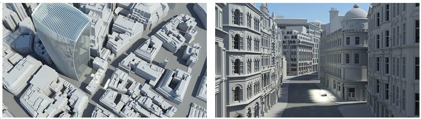
Figure 9 – Simulation of the real-time using the NVIDIA Iray technology
Implementation of ray-tracing continues its active development. In modern graphics cards for users can be partly traced images, but at the same time increasing the cost. The main problem today is that the graphics system with the implementation of this method are expensive and tracing in real time is not available to most users. But the rendering process can be accelerated by interpolation and parallel computing that significantly speed up time-consuming. Reduce the cost of such systems is possible to decrease the cost of hardware that will explore in this paper.
In writing this essay master's work is not yet complete. Final completion: July 2017. The full text of work and materials on the topic can be obtained from the author or his manager after that date.