
Abstract
The contents
- Introduction
- 1. The relevance of the topic
- 2.Purpose and research tasks, planned results
- 3. Overview of research and development
- Insights
- List of sources
Introduction
coal Reserves in the Donbas sufficient to ensure energy development for several hundred years. However, due to the development of the energy sector of the former USSR and in Ukraine in particular, over the last 15–25 years the emphasis was on the development of nuclear energy, and heat using natural gas and fuel oil. As for coal, the major power on this fuel was introduced 40–50 years ago and their technical level has remained virtually unchanged to the present time.
the Only type of combustion equipment, applied practically in power boilers of power plants of Ukraine, are chamber furnaces with liquid slag removal. The spread in Ukraine of furnaces with liquid slag removal due to the fact that the postwar development of the energy sector was connected with the construction of power plants on low-reactivity fuels, such as lean coal and ASH.
1. The relevance of the topic
the burning of coal degraded quality in the boilers of TP-100 units 200 MW arises the problem of reducing heat loss and improving boiler efficiency in the production of heat and electrical energy. The solution of this problem will allow to reduce specific fuel consumption and increase the efficiency of the main equipment of the unit.
When burning fuel in the vortex gas burners to reduce mechanical entrainment necessary to develop actions aimed at improving the mixing.
2. Purpose and research tasks, planned results
the Aim of the study is the analysis of power unit No. 5 boiler unit TP-100 of Starobeshevskaya TPP and improvement of burners to reduce fuel consumption
Main tasks:
- Analysis of burners.
- to analyze experimental data to identify the optimal option twist for burners.
- to Improve tehniko-economic indicators of the boiler operation.
Object of study: burner device.
research Subject: a study of the modernization of the burner apparatus, the improvement of mixture formation in the combustion of coals of degraded quality.
3. Overview of research and development
In the furnace of the boiler TP-100 of low-emission burners installed dust and gas with snail swirler of primary air vane swirler and the secondary air, in quantities of 12 pieces, a thermal capacity of 50 MW. Longitudinal section of the burner shown in Fig. 1.
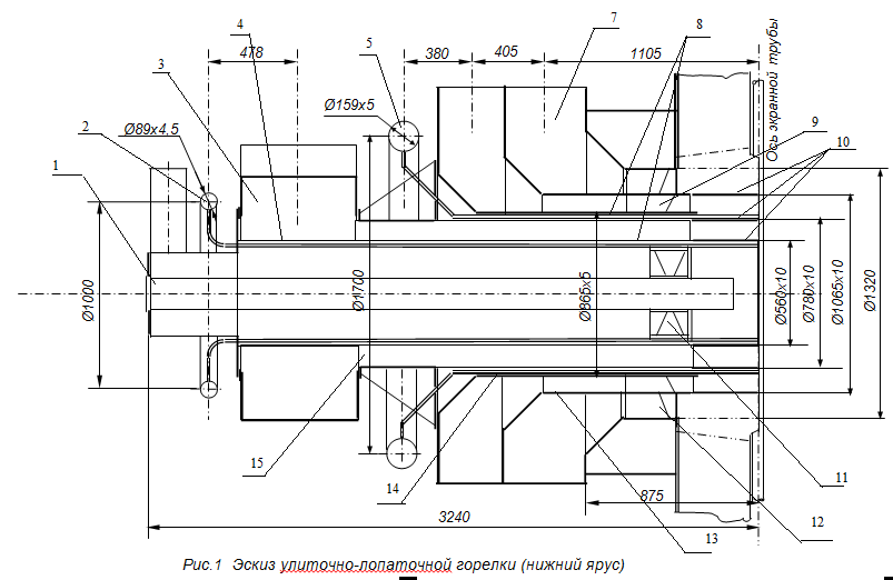
1 – pipe to install the oil burners Ø89×4,5mm; 2 – collector additional natural gas supply; 3 – snail primary air; 4 – Central pipe; 5 – manifold main supply of natural gas; 6 – inlet of secondary air in the inner channel; 7 – inlet of secondary air in the peripheral channel; 8 – ganapataye pipe Ø28×3 mm; 9 – retaining sheet 10 - the axial swirler of the inner channel of the blades with a smooth entry; 11 – high-temperature nozzles; 12 – axial swirler Central channel with straight blades; 13 – axial swirler peripheral channel of the blades with a smooth entry; 14 – intermediate secondary-air pipe; 15 – tube sensor SSW; 16 - primary air pipe.
the Intensity of turbulence of the air flow parameter characterizes the swirling flow. Dual-snail-blade vortex burners of dust-air mixture and secondary air reported a swirling motion with the same direction of rotation.
the twist Parameter is selected from conditions provide suction to the root of the torch is necessary for stabilizing the quantity of the flue gases. Enters the furnace through the swirlers-blades, that is, the parameter twist method of the swirl flow.
In Fig. 2 shows an axial vane swirler installed in the burner.
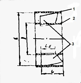
Figure 2 – 1 – rim; 2-sleeve; 3 – blade
Twist the air flow intensifitsiruetsa the process of mixing fuel with air to stabilize the combustion front due to the suction of hot gases from the furnace, contributes to more uniform results of air around the circumference, reduces the range of the torch and facilitates operation at low load.
Hydraulic resistance, structure and speed unevenness of the air flow, are highly dependent on the intensity of the twist, which when comparing these characteristics for all utanovleny burners in the furnace, the intensity of the swirling flow must be the same when you change the heat output of burners. The relative length of the neck of the burner and form the breach must also be the same.
Swirling air flow in a vortex burner is characterized by axial (Wa), tangential (Wt) and radial (Wr) velocity components. First – parallel to the axis of the cylindrical channel, the second – lies in the plane of the cross section and directed perpendicular to the radii, the third – parallel to the radii.
the Axial and tangential components are comparable to each other and can be equal or different, depending on the intensity of the swirling air flow. The radial component is so small that it is neglected in practical calculations.
D. N. Lyakhovsky offered all the swirling jet is divided into two classes [1]:
-
the
- weakly swirling jet, in any cross section of which the axial velocity on the axis is positive; the
- strongly swirling jets with reverse current in the axial region.
Air flow in swirl burners majority belongs to the second class.
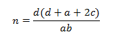
the Degree of twist of the air flow tangential and snail:

Where a - the width of the inlet pipe (the size perpendicular to the axis of the cylindrical channel);
b - length of the inlet pipe (the size along the axis of the cylindrical channel)
d - the diameter of the cylindrical channel of the burner.
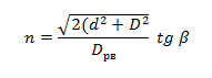
R. B. Akhmedov, based on the definition of the intensity of twist:

M - applied moment of momentum about the axis of the swirling flow; K– the movement of the air stream; g– the radius of the cylindrical channel, brought the value of the intensity of the swirling flow at snail cart air:
Here is the smallest distance between the continuation of the inner wall of the transfer tube and the cylindrical channel of the burner (depends on the position of the gate language)
the pressure Distribution and other parameters are determined by the dimensionless parameter of the integral twist, which remain constant along the jet. Along with the geometry of the burner by the ratio of the speeds and costs of primary and secondary air, the twist parameter has a significant influence on the shape of the torch, the angle of his erection intensity heat and mass transfer.
the Impact on the combustion process is possible in the initial phase of the formation of the torch. We are talking about the aerodynamics of the flue gases, it is the turbulence which depends both on the burner structure and the mutual arrangement of the burners in the combustion chamber.
In the channel air-dust mixtures by burning anthracite culm, Vd=12.1% of installed axial blade swirler. For swirling a secondary air swirlers vane set.
Axial blade swirler is calculated as follows:
Each burner within the specified limits ensures steady combustion and the stabilization of the front for the ignition (without pogasanii, pulsation, separation from the burners).
Documentary analysis of experimental data to identify the optimal setting of twist, for each of the 12 burners installed, showed the range of the angle of rotation of the blades in the inner and peripheral channels, which provides optimal parameters of the twist.
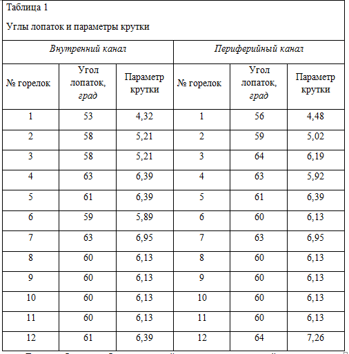
So, the angle of the blades in the channels of the burners of the lower layer has a significant difference, indicating a low quality of their production. Conducted process flow tests of burners of the data allowed us to determine the optimal parameters of rotation of the vanes, the swirler providing sufficient turbulence of the flow and stabilization of the flame. In the inner channel of the burner №1 angle is 53 °, and the burner № 4 – 63°, the twist parameter, respectively, and equal of 4,32 and of 6,39. In the peripheral channels of the burners of the lower tier corners in the burner №1 are °, burner №3 – 64°, and twist parameters, respectively, – of 4.48 and of 6.19.
In the burners of the upper tier corners between the output part of the vanes of the swirlers and the axis of the burners are within: internally – 59-63°, at the peripheral channels is 60-64°.
table 1 shows the optimum size of the angles between the output part of the vanes of the swirlers and the axis of the burners, as well as calculating the parameters of the swirling air currents of the respective channels.
Insights
Thus, providing the calculation obtained in the experiment, the angle of rotation of the blades on each burner, we have got the optimal setting of twist and as a result – improving the quality of mixture formation in the center of the torch.
heat Loss from mechanical underburning has decreased by 3.47% and 7,26%, boiler efficiency increased 4.1% and reached 86.22 percent. Stabilization of the torch
sources List
- D. N. Lyakhovsky, Influence of design parameters of circular burners on their resistance and the aerodynamics of the torch. KN. 2, vol. I. Mashgiz, 1947.
- R. B. AKHMEDOV. The intensity of the swirling airflow in vortex burners, "thermal Engineering", No. 6, 1962
- Belousov, V. N., Smorodin S. N., Smirnova O. S. the Fuel and theory of combustion/SPb., 2011 - p. 84
- Boyko, E. A., Thermal power plants (calculation and design of recuperative heat exchangers TPP): a tutorial. - Krasnoyarsk: the CPI KSTU, 2006. - 92 p.
- Yu. V. Ivanov, gas boiler unit , 1971 - p. 165