
Abstract
Содержание
- Introduction
- 1. Theme urgency
- 2. Goal and tasks of the research
- 3. Overview of research and development
- Conclusion
- References
Introduction
Improvement of heat exchangers is carried out in the framework of traditional structures through the modernization of the individual elements and towards the creation of fundamentally new devices. Improved apparatus should provide designs with high reliability in which the intensification of heat transfer that can be achieved using intensified heat transfer surfaces, such as fin and tube shaped differently, and the use of other methods of heat exchange. Improving the thermal efficiency of vehicles contributes to improving the aerodynamics of the tube bundles when the conditions for the uniform washing of the surface of the cooled heat transfer unit without dead spaces or inaccessible areas, as well as the elimination or consideration of the effect of leakage of coolant in the gaps and in addition to the intermediate partitions of the tube bundle. Improving the reliability of apparatus are solved, as a rule, by eliminating the drawbacks of the existing designs identified in the operation of devices. For example, the rational organization of the shell side coolant supply and distribution of the tube bundle can improve vibronadezhnost pipe systems.
1. Theme urgency
The main part of produced electricity is generated from steam power plants included in the units of thermal and nuclear power plants. Vapor condensation is accompanied by a significant drop in pressure at the same time the energy efficiency of a steam turbine plant is determined by the pressure difference between the steam inlet and outlet of the turbine. film mode condensation on the steam side and scale formation on the water side of the capacitor during the operation led to a significant deterioration of heat exchangers and the hydraulic characteristics of a capacitor, an increase of condensing pressure and "underproduction" electric power generating units of TPP.
2. Goal and tasks of the research
The aim is to research and develop technical solutions to improve the thermal efficiency and reliability of the condensing units of cogeneration turbines. Increased efficiency of the steam turbine and the condenser.
Main tasks of the research:
- Analysis of the impact of various factors on the efficiency and reliability of the condensing device.
- Assessing the impact of the final and initial parameters on the efficiency of the plant.
- Development of technical solutions to improve the efficiency of condensing units.
Research object: turbine condenser.
Research subject: study the modernization of turbine condensers.
3. Overview of research and development
One of the main sources of low-grade heat relief at thermal power plants (TPP) are condensers of steam turbines, where the condensation takes place in the turbine exhaust steam from the release of the latent heat of vaporization, which is given by means of a cooling fluid into the environment. The usual way to use water to dissipate heat is a direct pumping freshwater lake or river water through a condenser and then return it in natural reservoirs without taking into account the inevitable growth ohlazhdeniya.S water scarcity conducted research on the development of systems of cooling condensers with minimal water requirements or general waterless cooling systems.
In general, the cooling system of condensers can be divided into wet (waste heat is transferred to the cold water source via the intermediate heat transfer medium), dry (waste heat source is directly transferred to cold) and a hybrid (mokrosuhuyu) cooling system. According to most experts in the conditions of the cooling water shortages are the most promising and mokrosuhogo dry cooling system. Such cooling systems are used or are planned to be installed to the power station, located in shallow areas and in the areas close proximity to sources of fuel in the United States, Germany, France and the Netherlands.
In the US, for example, has been in operation unit of 330 MW air-cooled condenser on the TPP Wyodek (dry cooling system) and a unit with a hybrid (mokrosuhoy) cooling tower to the power station San Juan III. In order to increase the cooling capacity of the dry cooling system in the hot season it is usually connected additional system containing elements of evaporative cooling.
Next to energy research centers in the US carried out a comprehensive study of the new cooling system, in which the intermediate coolant instead of water is ammonia evaporating in the surface condenser and condensing turbine and then in a cooling tower, where the heat of condensation is transferred to the outside air. This system provides a significant reduction in installation costs with a slight increase in costs of the condenser. However, due to ammonia toxicity should provide appropriate security measures.
And developed another type dry cooling systems using ammonia as an intermediate in the coolant to transfer heat from the turbine exhaust steam in the surrounding air. The system is a heat pipe assembly filled with ammonia, which serve as a surface condenser, effectively transferring the heat of condensation.
Massachusetts Institute of Technology (USA) developed the cooler design, consisting of a rotating disc, half-submerged in the trays with the cooling water, covered with an oil film. Immersed half discs are heated in water and then cooled in a stream vozduha.Rassmotrim series of schematic diagrams of various capacitors cooling systems, actively developed at the moment.
In Fig. 1 shows an embodiment mokrosuhogo cooling system comprising one condenser surface, independent bundles 2 and 3 which by means of conduits 4 and 5 with the regulating and shutoff valves are respectively connected to six wet and dry cooling towers 7. The presence of the auxiliary piping 12, pump 8, 9, 10, 11 and the container 13 allows to regulate heat output of each tower depending on the ambient temperature. Each of the towers are mechanical traction 14.
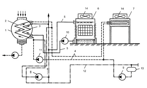
Figure 1 – System wet dry cooling condenser
In Fig. 2 shows an example mokrosuhogo cooling system using a coolant for an intermediate drycooler low boiling substance such as ammonia. In this scheme, the tube bundle between 2 and 4 dry cooling tower installed separator 5 for separating ammonia vapor-liquid stream at the outlet of the tube bundle 2 and the liquid ammonia feed conduit 6 to the input of the tube bundle 2. The condenser 1 is made two-part in each of one sections taken tube bundle 2 and 3, and each beam independently connected respectively to the dry and wet cooling towers.
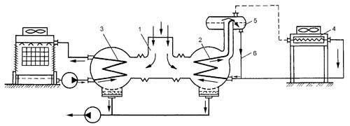
Figure 2 – mokrosuhogo condenser cooling system with a low-boiling substance as the intermediate heat carrier
On Fig. 3 shows a cooling system with parallel connection of wet and dry parts of the hybrid cooling tower. The housing 1 has a dry part 2 and part 3. Dry wet part 2 is made in several rows of tubes 4 are uniformly distributed in the upper airway windows 5. Wet part 3 represents evaporative cooling tower, located at the bottom of the housing 1. Water heated in the condenser 6, fed via conduits 7 and 8 are parallel flows in the wet and dry 2 3 parts of the tower.
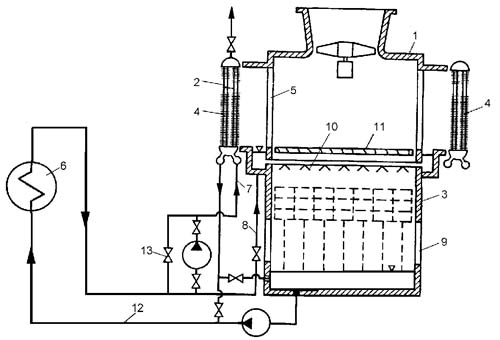
Figure 3 – condenser cooling system with parallel connection of wet and dry parts of the hybrid cooling tower
Water cooling is parallel to the air flow coming into the housing 1 respectively through the top 5 and bottom windows 9 airway. To reduce the loss of cooling water spray unit 10 on part 3 of water traps 11. Once placed in the cooling tower water through line 12 back to the condenser. The presence of valves 13 allows you to adjust the heat output of parts 2 and 3, depending on the meteorological environment.
Shown above mokrosuhogo cooling system can operate in two basic modes. In the first mode of operation provides for a wet cooling tower for a minimum time. As the outside temperature decrease rate of the cooling water on a wet cooling tower is reduced. The second mode provides for continuous operation of the wet cooling tower until until the outdoor temperature is reached at which the current vacuum operation can be ensured only with a dry cooling tower. At this temperature, wet cooling tower is switched off, and the heat load is completely transferred to the dry cooling tower. Mokrosuhie systems operating in the first mode, can save more water when used? Proc eed loss of energy, and systems operating in the second mode, save more energy by b? Brings more water lost to evaporation.
The dry cooling systems can distinguish two fundamentally distinct schemes of direct and indirect cooling.
In (Fig. 4) provides a direct dry cooling scheme with total reflux heat exchange surface.
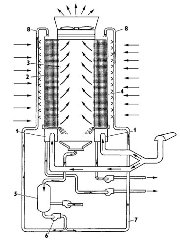
Figure 4 – Scheme of direct dry cooling condenser with full irrigation of the heat exchange surface
The system includes manifolds 1 provided with a vertically mounted two heat pipes, each of which is filled with coolant (e.g. ammonia), transmitting thermal energy from the turbine exhaust steam to the environment 3.
Evaporating part of the heat pipes are placed in steam collector 1 and the condensing portion 4 mounted vertically on the outside to form a plurality of rows of heat exchange surfaces, irrigated with water and the top side in the direction of movement of the cooling medium.
After the irrigation water collected in the heat transfer surface 5 and the container 6 by the pump 7 via conduits 8 the spray device again is fed to the heat exchange surface formed by condensing portions of the heat pipes 4 and are placed on the ribs. With irrigation, the heat exchange surface is convection-evaporative heat transfer from the tubes 2 to the ribs, and then to the water film and the heat exchange surface is washed by air.
In Fig. 5 shows an example of the dry indirect cooling circuit with peak coolant.
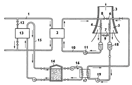
Figure 5 – Scheme of indirect dry cooling condenser with peak cooling
In the turbine exhaust steam enters through line 1 into the surface of the capacitor 2. The heat of condensation and intermediate coolant perceived environmental air is passed in two, placed in extraction tower 3, air heat exchangers 4 and 5, which by means of conduits 6 and 7 and the valve 8, 9 connected in parallel. The cooled in the tower 3 intermediate coolant returns through conduit 10 to condenser 2. The circulation of the coolant between the intermediate condenser coils 2 and 4 and 5, a pump 11 installed on the pipe 10. The maximum period for maintaining the electrical load on the turbine rated back pressure valve 12 opens, and part of the steam supplied to the surface peak cooler 13. Cooling and condensation of the vapor in the cooler 13 provided with a cold coolant accumulated in the bottom of the tank 14. The heated coolant in the cooler 13 via line 15 is returned to the top of container 14.
During the failure of the electrical load hot coolant from the tank 14 through line 16, enters the water-to-water heat exchanger 17; 5 with a heat exchanger 8 and valve 9 is disconnected from the heat exchanger 4 and the hot coolant in the cooling heat exchanger 17 is provided intermediate coolant stored in the circulating tank 18 and between the heat exchangers 17 and 5 with a pump 19.
Conclusion
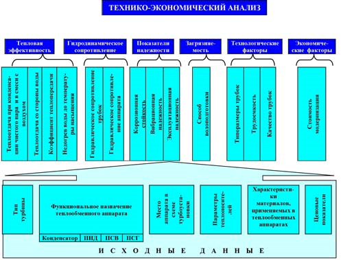
Improvement of heat exchangers steam turbines is one of the important tasks of power engineering and energy. Stricter requirements for weight and size characteristics of the power equipment, while increasing heat loads, speeds of working environments and corrosion of water activity as well as the possibility of contamination of the heat transfer surfaces are forcing developers and manufacturers of heat exchangers to look for new methods to improve their efficiency.
Below is a block diagram of an integrated study of measures to improve vocational heat exchange devices. The proposed integrated circuit includes a plurality of the main factors that determine the efficiency and reliability of the heat exchanger, and can be used as the design of new machines and devices at modernization in the field. To simplify the analysis, a block diagram is divided into specific groups of indicators, based on which the assessment is carried out and the effectiveness of a particular method, and the final decision is taken on the basis of a feasibility study, taking into account the totality of all these factors. The initial data for the analysis are the type of turbine, the type of heat exchanger and its place in the scheme of technological parameters of heat carriers, characteristic of pipe material, as well as various price levels. In addition, each heat exchanger should be considered not in isolation but as an organic element of the turbine installation. In addition, significant influence may have regulatory characteristics of a particular turbine fuel cost for a particular station and other indicators. Thus, the rationale for measures to improve the heat exchangers should be carried out on the basis of a comprehensive feasibility analysis of the turbine as a whole.
References
- Brodov Y., Savelev R., condensing steam turbine installation M.: Energoatomisdat, 1994.
- Martynenko O., Handbook of heat exchangers. Volume 2, Energoatomisdat, 1987. - 352 p.
- Shklover G., Milman O., study and calculation of condensing steam turbine units, Energoatomisdat, 1985. - 240 p.
- Bajan P., Handbook of heat exchangers, Mechanical Engineering, 1989. - 366 p.
- Berman S/., heat exchangers and condensing turbines device textbook. - M.: Mashgiz, 1959. - 428 p.
- Ryzhkin V., Thermal Power Plants: A Textbook for universities / ed. Y.Hirschfeld. - 3rd Ed. Revised. and ext. - M .: Energoatomisdat, 1987. - 328 p.
- Truhny A., Lomakin B., cogeneration steam turbines and turbine: a textbook for high schools. - M .: MEI Publishing, 2002 - 540 p.