
Abstract
Content
- Introduction
- 1. Theme urgency
- 2. Goal and tasks of the research
- 3. Induction motor fault diagnosis
- Conclusion
- References
Introduction
Induction motors are widely used in manufacturing, transportation, petrochemical, mining, power systems and so on due to their reliability and simplicity of construction, high overload capability and high effciency. Compared with direct-current motors, induction motors are more rugged, less expensive and require less maintenance. Therefore, they are the preferred choice for industrial motors [1].
However like any other machine, they will eventually fail because of heavy duty cycles, poor working environment, installation and manufacturing factors, etc.
Domestic and foreign experience shows that one of the most important factors to improve the economic industrial equipment efficiency is diagnostic tools application. Purpose of diagnosis – failures and malfunctions detection, maintenance of operational indicators within the established limits [2].
1. Theme urgency
Electric motors working reliability is decreases after repair with disassembly and replacement of details. Hidden defects, such as, squirrel-cage rotor bars crack and stator winding defection is problematic to detect [3].
The ultimate diagnostic goal depends on life cycle stage at which the engine technical condition is determined: during the production, operation or repair phase [4].
At present, there is a need to diagnose the state of induction electric motors in their operating process. Timely detected damage will avoid further development of the process, reduce recovery time, reduce maintenance costs, avoid equipment downtime, improve the efficiency of engines and production mechanisms. Therefore, the diagnosis of induction motor is a unique scientific and practical task.
2. Goal and tasks of the research
The master's work purpose is to review the existing diagnosting methods for induction motor and to determine the simplest and most qualitative of them.
Main tasks of the research:
- A literature sources review and the existing methods definition for induction motors diagnosing.
- Advantages and disadvantages of these methods.
- The optimal diagnostic method identification and development a scheme for its practical implementation.
Expected results:
- Determination the best method for diagnosing an induction motor during operation
- Development a scheme for the practical implementation of this method
- Calculation and selection of all necessary components.
- Practical implementation of this scheme
3. Induction motor fault diagnosis
Figure 1 shows the relative probability of occurrences of various faults in an induction machine.
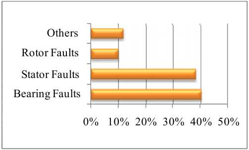
Figure 1 – Faults by % in an Induction Motor
A typical diagnosis system shown in figure 2 consists of a sensor assembly which provides the fault signal to a signal processing unit, which further sends its result to be analyzed by expert systems, where the fault is ultimately detected
Figure 2 – Diagnosis system of Induction Motor
(animation: 6 frames, 7 reiteration cycles, 73,8 kilobytes)
The ideal modern method for diagnosing electric motors must meet the following requirements:
- high reliability and accuracy of faults and motor faults detection;
- the possibility of detecting all or a significant part of electrical and mechanical motor damage and associated mechanical devices;
- carrying out diagnostic measurements remotely, which is important in cases where access to equipment is difficult;
- low laboriousness of diagnostic work (measurements) and ease of measurement;
- the performing analytical processing possibility of the obtained measurement results in a short time, with the use computer and software tools [5].
A number of sources highlight the motor current signature analysis (MCSA) [1], [5], [6], [7], [8], [9]. It uses for detecting faults of the induction machine, such as turn to turn fault in the stator, broken rotor bar and air-gap eccentricity
Motor current signature analysis is based on detection of current harmonics with frequencies that are distinguishing each category of fault. In additional, it does not need additional installation of measurement system. Broken bars cause the rotor asymmetry, the distortion of the rotor current distribution and therefore the changes in rotor magnetomotive force (MMF). A broken rotor bar fault has distinctive characteristic frequencies which can be calculated as

The per unit slip of the motor can be calculated as

Where fs and fr are supply frequency and motor frequency respectively, and р is number of poles. In case of broken bar, sidebands around the supply frequency can be expected in the phase current power spectrum. As a result, the first-order sidebands (k=1) are of particular significance in the detection of broken rotor bar fault. The left sideband fs(1-2ks) is due to electrical or magnetic rotor asymmetry caused by broken rotor bars while the right sideband fs(1+2ks) is due to the speed ripple or variation.
The amplitudes and presence of the sidebands depend on the physical position of the broken rotor bars, speed and load. The locations of the sidebands will shift outwards as the speed and load are increased. It is recognized that the sidebands might be observed when the motor has no broken rotor bar fault as rotor ellipticity and shaft misalignment could both induce rotor asymmetry to a certain extent. However, the sideband amplitudes formed in those cases are much smaller compared with those produced by broken rotor bar fault. In paper [6], two faulty motors were used, one with one broken rotor bar and the other motor with two broken bars. The rotors of these motors were drilled and used in the tests to simulate the broken rotor bar fault and then compared with a healthy motor.
Figure 3 and figure 4 show the two tested rotors with one broken bar and two broken bars respectively. Faults were induced by drilling carefully into the bars along their height in such a way that the hole cut the bar completely.

Figure 3 – Rotor with one broken bar

Figure 4 – Rotor with two broken bars
Figure 5 shows the current power under healthy and faulty motor at different loads. The sideband amplitudes of healthy motor are -27.27 dB (left) and -34.38 dB (right), while they are -16.19 dB (left) and -19.03 dB (right), and -13.01dB (left) and -14.80 dB (right) in case of two broken bars, The difference amplitude of left sidebands between healthy and two broken bars is 14.26 dB at 75% full load. It is clear that the amplitude of side band increase as the load and fault severity increase and that the fault can be best detected under higher loads
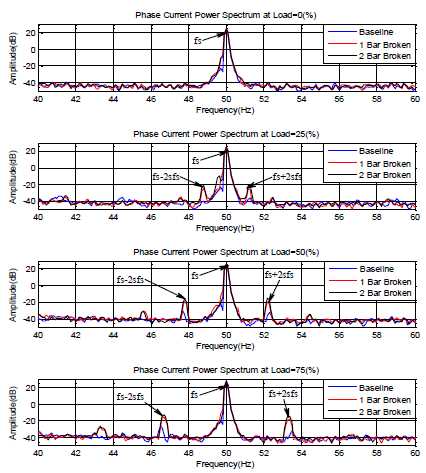
Figure 5 – Phase current power spectra under different load conditions
In paper [7] a similar experiment was conducted, but with three damaged rotor bars.
Motor Vibration Analysis is also effective [6], [7], [9].
Accurate speed and mains frequency as well as fault related frequencies can be determined by using motor vibration spectrum. There are always inherent rotor mass unbalance and shaft misalignment leading to frequency components at motor rotation frequency and its harmonics in vibration spectrum. As mentioned earlier, in the case of broken rotor bar, there is a speed oscillation with frequency 2sfs. This oscillation acts as a frequency modulation on rotation frequency and two side band frequencies (fr - 2sfr) and (fr + 2sfr), appear around fr in vibration spectrum. When the rotor circuit unbalance increases, the magnitude of speed oscillation as well as the magnitudes of side band frequencies increase too. Therefore, the magnitudes of (fr ± 2sfr) can be good measures for broken bar detection. Paper [6] has presented this method to detect broken bar faults by using vibration.
Figure 6 show the power spectrum motor vibration under different load. As can be seen from the figure, sideband differences between normal and broken rotor bar on both sides of the rotor speed at 75% full load. Under the normal condition, amplitudes of the first-order sidebands are around -59.47 dB (left) and -55.18 dB (right), respectively. With one broken bar fault the sideband amplitudes are increased to -57.81dB and -54.52 dB, a difference of 4.29 dB, while sidebands are -53.35 dB and -49.05 dB in case of two broken bars.
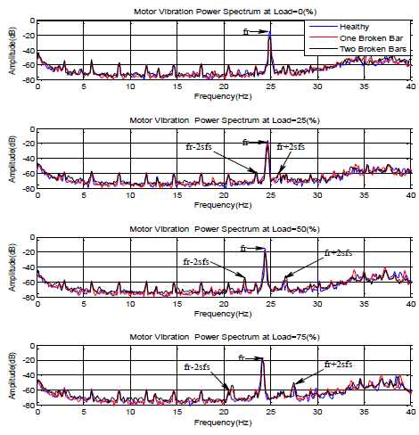
Figure 6 – Motor vibration power spectra under different load conditions
Paper [7] has presented engine bearing damage detection thanks to motor vibration analysis.
In paper [7], [8] allocated also Intelligent Techniques like Fuzzy logic systems, Artificial Neural Networks, Neuro-Fuzzy System
Figure 7, a schematic of Neural Networks for condition monitoring of an induction motor is presented [7].
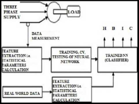
Figure 7 – Neural network schematic for condition monitoring of induction motor
We have developed a method for fault detection and diagnosis of switching device mis?ring in a voltage-fed PWM inverter induction motor drive. The method is based on the Concordia stator mean current pattern (Figure 8).
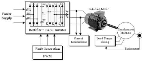
Figure 8 – Schematic for condition monitoring of induction motor with a voltage-fed PWM inverter
Methods based on the analysis of acoustic oscillations, methods based on measurement and analysis of magnetic flux, methods based on measurement and analysis of temperature, methods of mechanical components diagnostics, methods of diagnosing the state of isolation are also known [9].
Comparing all technical, methodological and economic factors, we can conclude that for practical implementation the most promising are the methods of diagnosis based on the analysis of electrical parameters of the engine, namely the signature of voltages and currents
To derive the technical requirements for the diagnostic device parameters from the signals of the stators' currents and voltages of induction motor, a number of sources were examined and analyzed [5], [9], [10], [11]. So the sampling frequency of the measuring channel must be in the range from 1500 to 3000 Hz.
Conclusion
There are already many methods for diagnosing the state of an induction motor during its operation. In this paper, the most famous of them were considered. The most promising for practical implementation are the methods for diagnosing an induction motor, based on the analysis of voltage and current signature. And also has been put requirement for the sampling frequency of the measuring channels for this method.
Further studies focused on the following aspects:
- Select the optimal structure of the practical implementation scheme of the diagnosting method for induction motor;
- Calculation and selection of necessary equipment;
- Presentation of the working diagram for the practical implementation of the diagnostics of an induction motor during its operation
This master's work is not completed yet. Final completion: June 2017. The full text of the work and materials on the topic can be obtained from the author or his head after this date.
References
- Fang Duan Diagnostics of rotor and stator problems in industrial induction motors// Adelaide University: [Электронный ресурс]. – URL: https://digital.library.adelaide.edu.au/dspace/bitstream/2440/65202/8/02whole.pdf
- Ширман А.Р., Практическая вибродиагностика и мониторинг состояния механического оборудования/ Ширман А.Р., Соловьев А.Б. – Москва, 1996. 276с.
- Полковниченко Д.В. Послеремонтная оценка технического состояния короткозамкнутых асинхронных электродвигателей// eNTUKhPIIR: [Электронный ресурс]. – URL: http://repository.kpi.kharkov.ua/bitstream/KhPI-Press/11713/1/EE_2005_1_Polkovnichenko_Posleremontnaya.pdf .
- Генкин М.Д. Виброакустическая диагностика машин и механизмов/ Генкин М.Д., Соколова А.Г. – М.: Машиностроение, 1987. 288 с.
- Петухов В.С Диагностика состояния электродвигателей на основе спектрального анализа потребляемого тока/ Петухов В.С Соколов В.А.// [Электронный ресурс]. – URL: http://www.tesla.ru/publications/files/051.pdf .
- A. Alwodai, F. Gu, A.D. Ball A Comparison of different techniques for induction motor rotor fault diagnosis/ 25th International Congress on Condition Monitoring and Diagnostic Engineering, IOP Publishing, Journal of Physics: Conference Series 364, 012066, 2012.
- Partha Sarathee Bhowmik, Sourav Pradhan, Mangal Prakash Fault diagnostic and monitoring methods of induction motor: a review/ International Journal of Applied Control, Electrical and Electronics Engineering (IJACEEE), Vol. 1, no. 1.
- Demba Diallo, Mohamed Benbouzid, Denis Hamad, Xavier Pierre Fault detection and diagnosis in an induction machine drive: A pattern recognition approach based on concordia stator mean current vector// Archive Ouverte HAL-UPMC: [Электронный ресурс]. – URL: http://hal.upmc.fr/file/index/docid/526691/filename/IEEE_TEC_2005_DIALLO.pdf.
- Сидельников Л.Г. Контроль технического состояния асинхронных двигателей в процессе эксплуатации/ Сидельников Л.Г., Афанасьев Д.О. – Пермский национальный исследовательский политехнический университет.
- Habtler T.G. и Harley R.G. Diagnostics and intelligent controls in electrical systems – Georgia Institute of Technolgy/ АРЕС 25 February 2004.
- Сивокобыленко В.Ф. Диагностика асинхронного электропривода по данным измерений рабочего режима/ Сивокобыленко В.Ф. Полковниченко Д.В., Кукуй К.А. – Донецкий национальный технический университет: [Электронный ресурс]. – URL: http://ea.donntu.ru/bitstream/123456789/7204/1/7_2003.pdf.