
Abstract
Content
- Introduction
- 1. Actuality of the theme
- 2. The impact at the torque of the turbine by means of emergency control.
- 3. The impact of emergency control on the excitation systems of synchronous generators
- 4. Software for investigation of emergency control facilities.
- Conclusions
- References
Introduction
The emergency control should solve the following tasks:
- Avoiding the disruption of the stability of the parallel operation of the power system.
- Elimination of the asynchronous mode, if the stability violation was not prevented.
- The values of voltages, currents and frequencies should not exceed the permissible limits.
The main and paramount task is the first of the above, since sustainability in most cases is the main factor that provides solutions to other tasks.
To solve the problem of ensuring dynamic stability is to prevent the transition of relative angles between the EMF vectors of synchronous machines beyond the permissible values throughout the entire emergency process until the onset of a new steady state.
1. Actuality of the theme
The main aspects of the efficient functioning of the electric power system are reliability or stability (the reliability of parallel operation is defined as the damage to consumers that is the result of an emergency power failure for a given period of time) and survivability (the property of the power system, through which the power system can withstand severe emergency disturbances, preventing further development of accidents) are provided, as a rule, by a number of such events:
- Such, in which the generating capacities and transmission capacities of the transmission lines must be reserved;
- Optimization of operating modes of power systems taking into account hydro resources balance and fuel resources;
- Rational location of energy objects;
- Upgrading and modification of dispatch control automation;
- Increase in the level of qualification and production discipline of personnel working at power facilities, etc.
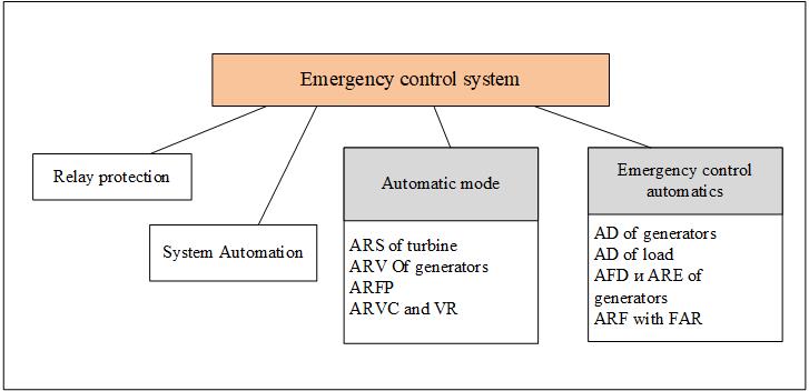
Figure 1 – Elements of the emergency control system
There are the following controls: switching type (switching on / off of power system elements); with the change of the turbine moment by increasing or decreasing the supply of steam or water; change of excitation of synchronous generators and compensators; change in the operating mode of the converter devices in the transmission, distribution and consumption system. [1]
Improvement and improvement of the quality of the work of the main automatic emergency control means is the key to the correct and uninterrupted operation of the EPS elements, also it should not be forgotten that it is necessary to develop and implement new additional control devices directly affecting the transient processes in the power systems.
2. Impact of emergency control at the time of the turbine
The means of emergency control of the impact at the time of the turbine are: impulse discharge of turbines, limiting the turbine's power, boosting the power of the turbine. The force of influence at the time of the turbine depends on the characteristics of the boiler turbine unit. In Fig. 3 shows a simplified diagram of the power unit, in which the following abbreviations for the names of the units and control devices are used: HPC – high-pressure cylinder (active-type turbine) MPC – medium pressure cylinder (includes housing with exhaust ports, rotor and directing device) LPC – low-pressure cylinder turbines; HSRCI – high-speed reduction cooling unit; ARS – automatic turbine speed regulator; EGC – electrohydraulic converter; SPR – steam pressure regulator; SRHG is a system for regulating the steam generator (boiler). Each power unit is equipped with an autonomous speed control system, and is directly included in the automatic frequency and power control (ARFP) system. Automatic frequency discharge (AFD) is the most important part of automation. If there is a decrease in frequency, it will not allow you to go beyond the unacceptable limits. If at the same time in the part that has been separated, there is no reserve of power in the form of underloaded aggregates, then it is very likely that an unacceptable reduction in frequency may occur. In this case, it should be understood that the boiler units must provide a reserve of turbine power. The possibility and speed of commissioning a reserve in thermal power plants depends on many factors: the adopted method for regulating turbine power, the type of boiler unit execution (direct flow, drum, with natural circulation, forced circulation), the technical condition of the thermal equipment. [3]
AFD with a certain reduction in frequency due to the emergence of a deficit of active power acts on the shutdown of a part of possibly less responsible energy consumers. In modern power systems, the most common cause of power shortage is an emergency shutdown of the line linking the scarce area to the rest of the power system.
As is known, each power unit can be included in the system of automatic frequency and power control (ARCM). The automatic control of the turbine speed not only ensures the necessary quality of electric power, but also prevents the avalanche of the frequency, thus being a very important measure for ensuring reliability.[3]
The increase in stability by changing turbine power is achieved in two ways: increasing turbine power or by reducing (unloading) the turbine's power. Unloading of turbines is used to maintain the static and dynamic stability of the parallel operation of the power system and allows a sharp acceleration of the resynchronization of the station or power system.
In some situations, turbine control can lead to a noticeable redistribution of power in the after-failure mode, reducing the effects of generator shutdown or load disconnection. The influence of the frequency control system can also be unfavorable. At the same time, ARCHM is due to the flow restriction system, which in many cases prevents the breaking of stability during spontaneous and emergency line overloads. Boiler automatics can also have an adverse effect, in particular the implementation of steam pressure control to maintain a constant pressure in front of the turbine. As the frequency decreases, the vapor pressure in front of the turbine begins to fall, which activates the regulator, which closes the valves and, accordingly, reduces the turbine's power. [3]
Thus, after a few minutes there is a spontaneous unloading of the power units, which leads to a repeated decrease in the frequency and is fraught with the danger of instability breakdown and the development of the accident. The regulation of the power unit with fully open valves with power control through changing the parameters of the steam virtually eliminates frequency fluctuations. As a result, the regulating effect of generation in the power system is significantly reduced, and the problem of keeping the frequency in emergency conditions is assigned to the means of emergency control [4]
3. The impact of emergency control on the excitation systems of synchronous generators
The forced excitation is not given by the excitation regulator (ARV) and not by the special forcing device, but supplemented by all this and is provided by the devices of the APNU (Automation for preventing stability violation). This type of PV is required only if ARV does not give a boost in the conditions when it is necessary.[1]
Automatic strong excitation regulators are used to increase the stability of parallel operation of turbo and hydro generators of power plants connected to the power system by long, heavily loaded transmission lines. These ARVs also make it possible to compensate for the unfavorable effect on the stability of the somewhat increased reactances of new powerful turbo-generators with direct cooling of the windings. [2]
In general, continuous control systems are used. These systems, especially the strong-action stimulation (ARE) regulators, provide a significant increase in static stability and sufficiently correct excitation control during transient processes. According to the principle of formation of the control effect, they are divided into two groups. One of them uses as input parameters the voltage deviation ΔU on the generator busbars or on the busbars of the higher voltage from the set value, the frequency deviation Δf at the generator terminals from the initial value and their derivatives. The second group uses the current or generator current deviations ΔI from the initial value and the current derivatives. [2]
An increase in the dynamic stability of power transmission is achieved by a rapid increase in the excitation current to its maximum permissible value-the so-called forced excitation of a synchronous generator. With the help of devices of relay automatic control of excitation, the excitation of the generator is forced. [6]
Regulation of excitation of the generator from the point of view of its influence on dynamic stability can be considered qualitatively. In Fig. 1.3, the thick line shows the areas in the case of stability failure during operation without regulation of the excitation. [7]
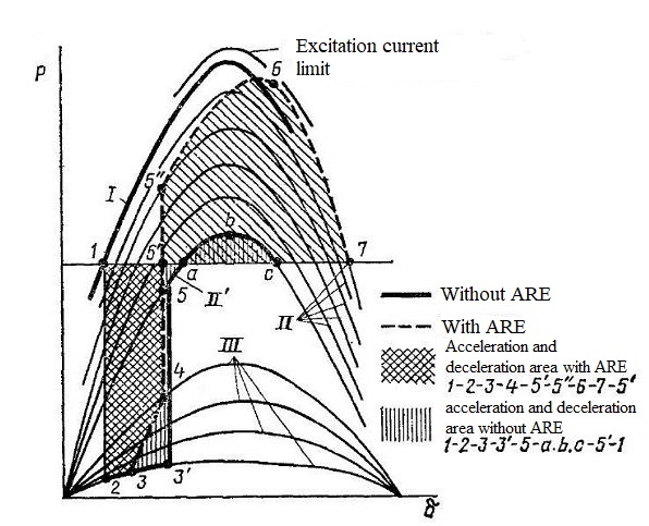
Figure 2 – The effect of boosting excitation (function P=f(δ))
The forced excitation allows keeping the generator in synchronism in the first cycle of oscillations. In the second cycle of oscillations, the forced excitation must be removed. If this is not done, then it is very likely that there will be a breakdown in the second cycle of oscillations (Figure 1.3). [7]
An analysis of the emergency control that affects the excitation of the generator makes it possible to conclude that expediency should be justified on the basis of preliminary studies depending on the specific operating conditions of the electric power system. [8].
4. Software for investigation of emergency control facilities.
The software developed in this work must satisfy the following requirements:
- The software (software) should provide an opportunity to assess the impact on the characteristics of the turbine and generator based on calculations of electromechanical transients in the electric power system.
- On the basis of the ratios of excess kinetic energies, which the rotor of the equivalent generator acquires during the entire transient process (area method), using the angular power characteristics, the conditions of conservation or violation of synchronous dynamic stability must be estimated.
- There should be a calculation of the angular power characteristics for all the operating modes of the electrical system:
- normal initial mode, when all possible connections between the transmitting and receiving parts of the electric power system are included;
- emergency mode caused by the occurrence of short circuits on power lines;
- post-emergency mode, which occurs after the disconnection of all lines on which the damage occurred;
- The software should provide for the possibility of investigating the influence of ИРТ at various pulse durations and the different number of unevenness of these pulses, their timeliness, and also the possibility of investigating the forced excitation of the generator in the second and third cycles of oscillations.
- There must be a calculation of short-circuits of various types (three-phase, two-phase, two-phase to ground and single-phase) at any distance from the controlled object (turbogenerator).
- To assess the conditions for saving the CDS in the software, it is necessary to determine the dependencies of the active powers given by the generator, as well as the dependence of the time variation of the angular positions of the rotor during the transient process.
- Calculation of the change in the angle of departure of the rotor in time must be performed on the basis of integrating the differential equation of motion of the generator rotor by numerical methods.
- The duration of the calculation of the transient process should cover 2 to 3 cycles of rotor swings in the transient mode, since under certain conditions the dynamic stability may not be violated in the first and in the second or third cycle of oscillations.
- The software should be developed using software packages for PC, which allow the most simple solution of differential equations and graphically visualize the dependence of the power angular characteristics and the time variation of the rotor angular positions of the generator.
The software was created in the mathematical package Mathcad. He is an excellent assistant in the solution of algebraic and differential equations with both constant and variable parameters, allows analyzing functions, searching for their extremums, numerical and analytical differentiation and integration, derivation of tables and graphs in the analysis of solutions found. There are also programming elements in the package. The programming language built into the package is easily mastered and allows solving a variety of rather complicated tasks and is also a serious tool for calculations. Therefore, the latest versions of MathCAD have a not very powerful, but very elegant own programming language. MATHCAD is a universal mathematical package designed for performing engineering and scientific calculations. The main advantage of the package is a natural and understandable mathematical language, on which the assigned tasks are formed. Combining a text editor with the ability to use a common mathematical language allows the user to obtain a finished output document. The package has a wide graphics capabilities. The ability to create animations was very helpful when writing this work. Thus, when checking the electric power system for stability, it is very easy to determine at what values this stability was violated.
Conclusions
The software developed is a software tool for impacting the turbine and exciting the generator. In these programs, research was carried out on the emergency control system of the EPS. However, it should be borne in mind that this software allows only to supplement and correct the actions of the automatic control system in various emergency situations with enhanced transient processes.
Master's work is not yet complete. This abstract will be amended during its completion. Tentative completion of work: May 2018. The finished work can be obtained from the author of the work or his supervisor after the official defense of the master's thesis with the appropriate permission.
References
- Кощеев, Л.А. Автоматическое противоаварийное управление в электроэнергетических системах / Л.А. Кощеев. – Л.:Энергоатомиздат, 1990. – 145 с.
- Глускин, И.З. Противоаварийная автоматика в энергосистемах / И.З. Глускин, Б.И. Иофьев. – М.:
Знак
. 2009. – 568 с. - Окин, А.А Противоаварийная автоматика энергосистем / А.А. Окин. – М.: Издательство МЭИ, 1995. – 212 с.
- Совалов, С.А. Противоаварийное управление в энергосистемах / С.А. Совалов, В.А. Семенов. – М.: Энергоатомиздат, 1980. – 416 с.
- Веников, В.А. Переходные электромеханические процессы в электрических системах / В.А. Веников. – М.: ВШ, 1985. – 536 с.
- Овчаренко, Н.И. Автоматика энергосистем: учебник для вузов.– 3-е изд., исправленное / Н.И. Овчаренко; под ред. чл.-корр. РАН, докт. техн. наук, проф. А.Ф. Дьякова.– М.: Издательский дом МЭИ, 2009. – 476 с.
- Куликов, Ю.А. Переходные процессы в электрических системах: Учеб. пособие / Ю.А. Куликов. – Новосибирск: НГТУ, М.: Издательство
Омега-Л
, 2013. – 384 с. - Колесник, Г.П. Переходные электромеханические процессы в электроэнергетических системах : учеб. пособие / Г. П. Колесник ; Владим. гос. ун-т. – Владимир : Изд-во Владим. гос. ун-та, 2008. – 116 с.