
Abstract
Содержание
- Introduction
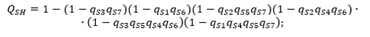
- 1. Formulation of the problem
- 2. Purpose, analysis of studies and publications
- 3. Research results
- 4. Example
- Conclusions
- References
Introduction
Using the concept of the cross section
, minimum cross section
, method for estimating the reliability of structurally complex systems whose elements can be in three inconsistent states: operable, failed (type failure open circuit
and failure of type short circuit
) is proposed.
An example of calculation is given.
Keywords: system, minimum cross section, complex scheme, probability, load node.
1. Formulation of the problem
To assess the reliability of complex non-renewable systems, the elements of which can be in three incompatible states, the minimum cross section
method is using.[1–2].
This method helps to evaluate the reliability of systems whose elements can be in three inconsistent states (operable, inoperative – type failure: open circuit
, inoperative – type failure: short circuit
),
which allow to take into account failures in the operation of protective switching devices and significantly improve the accuracy of calculations.
2. Purpose, analysis of studies and publications
Objective: improvement of the method for assessing the reliability of complex non-renewable systems, the elements of which can be found in two incompatible states.
To assess the reliability of complex non-renewable systems, the elements of which can be in three incompatible states, three methods are known based on the use of:
decomposition of a complex structure with respect to a base element, applying the triangle-star
and star-triangle transformations, and using the algebra of tuples.[3–6]
All proposed methods are rather difficult to use for engineering calculations, so the improvement of the
minimum cross section
method will allow to obtain a lower evaluation of the probability for failure-free operation of the systemwith considering two types of incompatible failures of its elements.
3. Research results
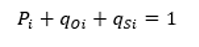
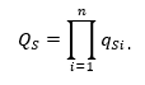
We denote by Pi the probability of failure-free operation of the i
-th element of the system,
qOi – is the probability of failure in the i
-th element of the open circuit
type,
and by qSi – is the probability of failures in the i
-th element of the short circuit
type. These three states constitute a complete group of incompatible events.
 |
(3.1) |
The index O
и S
n the formula indicate that element faults that lead to faults such as open circuit
, or faults of the type short circuit
, respectively.
In that case, if the elements of the system are subject to two types of incompatible failures: failure such as an open circuit
or short circuit
failure then the probability of its failure during the time t can be determined as follows [4]:
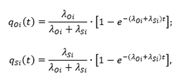 |
(3.2) |
where λOi,λSi – are the failure rate constants for the i
-th element, taking into account its failures such as open circuit
and short circuit
type, respectively;
t – current time of the i
-th element of the system.
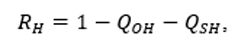
For non-renewable systems, the elements of which can be in three incompatible states, the formula:
 |
(3.3) |
where RH – is the lower estimate of the probability that such random events will not occur that result in a disconnection or an end-to-end fault current between the Input
and Output
nodes of the replacement circuit;
QOH,QSH – is the lower estimate of the probability that a disconnection will occur or an end-to-end fault current flows between the Input
and Output
nodes of the replacement circuit, respectively.
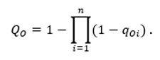
By a simple scheme of substitution of a system, we will take a one whose elements can be connected: sequentially, parallel, sequentially parallel, or parallel-sequential.
For a simple scheme of substitution of a system consisting of n
logical connection of elements, failure of the type open circuit
any of the n
elements (i = 1...n), leads to disconnection between the Input
and Output
.
If the probability of failures of the elements of the substitution circuit qOi is given, then the probability of disconnection between the nodes Input
and Output
QO is defined as follows:
 |
(3.4) |
If the probability of failure of the elements of the substitution circuit qSiis given, then the probability QO of that between the Input
and Output
nodes of the replacement circuit will pass the through fault current, we find using the formula:
 |
(3.5) |
Using the formulas (3-5), we find for the system that consists of n
logically sequential connection of the elements of the probability Rn that such random events will not pass, resulting in a disconnection or passing through fault current between the nodes Input
and Output
of the replacement circuit:
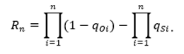 |
(3.6) |
For a simple
scheme for replacing a system that consists of m
ogically parallel elements, a failure of the type open circuit
in each of the j
elements (j = 1...m), causes the connection between the Input
and Output
.
If the probability of failure of the elements of the substitution circuit qOiis given, then the probability QO that the connection between the Input
and Output
nodes will be broken is found using the formula:
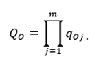 |
` (3.7) |
If the probability of failures qSj, (j = 1...m) of the elements of the substitution circuit is given, which consists of m
logically parallel elements, then QS – is the probability that an end-to-end fault current flows between the Input
and Output
terminals of the replacement circuit, formula:
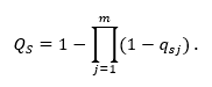 |
(3.8) |
Substituting formulas (7-8) into formula (3), we find that for a system that consists of m
logically parallel elements, the probability Rm is that such random events do not pass, resulting in a break connection or an end-to-end fault current between the nodes Input
and Output
of the replacement circuit:
 |
(3.9) |
Formulas (7) and (10) are valid if the following conditions are satisfied: qOi + qSi < 1, qOj + qSj < 1 and obtained in various ways [4–5].
Under a complex
scheme of substitution of the system, we mean a one that includes at least one group of elements connected in the form of a bridge
structure [11].
4. Example

Figure 1 – System replacement scheme
For the scheme of substitution of the system in Fig. 1 the following initial data are given :
 |
Define the lower bound RH
of the fact that there is no disconnect or an end-to-end fault current between the point Input
and Output
of the substitution circuit.
Using the notion minimum section
, the circuit of Fig. 1, the minimum section
scheme, taking into account failures of type open circuit/q> will take the form:
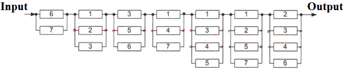
Figure 2 – The scheme minimum section
when accounting for the failure of elements of the type open circuit
Using the replacement circuit of Fig. 2, formulas (4),(7) we find:
 |
We substitute in the obtained formula the values: qOi (i = 1...7), given in the example condition, we obtain:
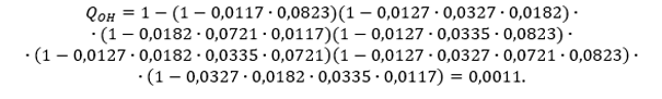 |
Using the notion minimum section
, the circuit of Fig. 1, the minimum section
scheme, taking into account failures of type short circuit/q> will take the form:
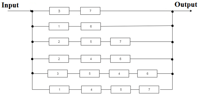
Figure 3 – The scheme minimum section
when accounting for the failure of elements of the type short circuit
Using the replacement scheme obtained in Fig. 3, formulas (5), (8), we find the lower bound QSH of the probability that an event will occur in which an end-to-end fault current passes between node
Input
и Output
of the replacement circuit:
 |
Using the initial data of the example, we substitute them in the obtained formula:
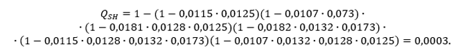 |
The probability that there will be no disconnection or the through fault current between node
Input
и Output
of the substitution circuit will be found using formula (3):
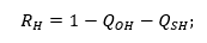 |
We substitute the obtained values QOH and QSH in the formula and define:
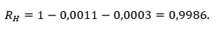 |
A similar result was obtained in solving this problem using an exact calculation method using the method of decomposition of a complex structure by the basis element [3].
Conclusions
1. An engineering technique for calculating the reliability of complex non-renewable systems is proposed, the elements of which can be in three incompatible states.
2. The accuracy of the proposed methodology for highly reliable systems (the probability of failure of elements of the substitution scheme is less than or equal to 0.1) is not inferior to the exact, tried and tested methods.
References
- Надежность технических систем: Справочник Ю.К. Беляев, В.А. Богатырев, В.В.Болотин и д.р.; Под ред. И.А. Ушаков. – М.: Радио и связь, 1985. – 608с.
- Рябинин И.А. Надежность и безопасность структурно сложных систем. СПБ.:Изд-во С. – Петербург ун-та, 2007. – 276с.
- Ковалев А.П., Спиваковский А.В. Применение логико-вероятностных методов для оценки надежности структурно-сложных систем. Электричество №9, 2000. – с.66-70.
- Диллон Б., Сингх Ч. Инженерные методы обеспечения надежности систем: Пер.с англ. – М.: Мир, 1984. – 318с.
- Ковалев А.П., Спиваковский А.В. О преобразовании «Звезда-треугольник» прирасчетах надежности сложных по структуре схем. Электричество №10, 1998 – с.70-74.
- Кулик Б.А. Логико-вероятностные методы и алгебра кортежей. – В сб.: Теория иинформационная техника моделирования безопасности сложных систем, – Санкт-Петербург: ИПМАШРАН, Препринг 123, вып. 1995, вып 5.
- Нечипоренко В.И. Структурный анализ систем (эффективность и надежность) – М.: Советское радио, 1977. – 214с.
- Эндрени Дж. Моделирование при расчетах надежности в электроэнергетическихсистемах: Пер. с англ. /Под ред. Ю.Н. Руденко М.: Энергоатомиздат, 1983 – 336с.
- Фонин Ю.А., Харченко А.М. Расчет надежности систем электроснабжения. – Электричество, 1982, №8 с.5-10.
- Белоусенко И.В., Ершов А.М., Ковалев А.П., Якимишена В.В, Шевченко О.А. О расчете надежности систем электроснабжения газовых промыслов. Электричество, 2004, №3. с.22-27.
- Ковалев А.П., Сердюк Л.И. Метод расчета надежности сложных схем систем электроснабжения с учетом восстановления элементов. – Электричество, 1985, №10 с. 52-53.