
Abstract
Content
- Introduction
- 1. Theme urgency
- 2. Goal and tasks of the research
- 3. Classification of robots and the scope of their application
- 3.1 Basic concepts and definitions
- 3.2 Functionality and scope of robotic manipulators
- 4. Diagram, and the constituent elements of the manipulator
- 4.1 Functional diagram of manipulators
- 4.2 Drive selection
- 4.3 Controller selection
- References
Introduction
In the modern world, the main direction of industrial development is the automation of production. This contributes to the growth of its efficiency by improving the quality of its products, as well as reducing the share of workers employed in various spheres of production.
One of the main elements of automation of industrial enterprises is the use of robotic complexes consisting of mechanical manipulators and control systems.
The use of such a robotic complex in the production process makes it possible to rationally approach the use of labor resources, improve the quality of the production process operation, reduce the time costs for its implementation, reduce the cost of production by reducing the percentage of marriage and reducing non-production costs (overtime and overtime work) increase output, improve production efficiency in general [1]. The use of such automation systems poses higher requirements for the manufacturability of products, to the system of technical training of production and the qualification of personnel.
1. Theme urgency
Robotics – a very extensive field of engineering practice, and recently it is increasingly expanding. The very concept of a robot
acquires a deeper meaning, in comparison with the one that was invested in it earlier.
Despite the universality of the term robot
and the associations caused by this term among non-specialists, the vast majority of robots used in industry are manipulators controlled by microprocessor controllers [2].
A manipulation robot is a technical device equipped with manipulators and capable of independently performing various mechanical operations in its working space. This is the broadest class of robotic devices. This includes all industrial robots (IR), as well as manipulation robots (MR), designed to replace a person in cases where it can not be present at the site of the operation or perform it independently – under water, in outer space, in conditions of increased radiation and the like. These tasks always place strict demands on industrial robots on a number of criteria: accuracy of position measurements, positioning accuracy, number of degrees of freedom and mobility of links. In this regard, the development of both the manipulator of the IR.
They are a complex electromechanical object with a number of features. First, manipulation robots are characterized by a complex kinematic structure that contains many independent or interconnected links. Secondly, changing the position of the latter in space affects the physical forces acting on the manipulator. Thirdly, there is a need for synchronous control of a large number of motors [8].
In connection with the presence of these features, for the introduction of MR in the production process, specially developed control systems are required. They serve to organize the interaction between the human operator and the MR, and ensure the execution of the processes necessary to automate the technological operation.
As a result, the problem of synthesis of kinematic, geometric parameters and the development of methods for their calculation become urgent [8].
2. Purpose and objectives of the study
Thus, the aim of the work is the development and research of the control system for the robot manipulator Katana
by Neuronics AG (Switzerland).
To achieve this goal, it is necessary to solve the following tasks:
- Analyze common approaches and determine the requirements for the management of robotic manipulators.
- Investigate the features of kinematics (calculate the direct and inverse problems of kinematics) and dynamics of the manipulator, and also to form its mathematical model.
- Develop and investigate the manipulation robot control system.
- Develop and design a user interface for the program management of the
Katana
manipulator.
3. Classification of robots and the scope of their application
3.1 Basic concepts and definitions
The manipulation robot is a multi-level, multi-functional manipulator designed to reproduce some working functions of human hands for the purpose of performing various works [1].
In its structure, the manipulator is a multi-tiered machine, between its individual elements there are mechanical links. Depending on the field of application, various schemes for constructing the mechanical part of the manipulator can be used, but the basic design is a sequence of links connected by rotational/translational pairs [2]. Most of the currently produced manipulators are among the robots with a rotational coordinate system. They provide the greatest volume of the working area in which movement can be carried out. Their structure allows you to achieve a given position and orientation of the working body, including when imposing restrictions on possible movements that occur when obstructions exist in the work area.
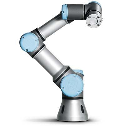
Figure 1 – Universal Robots Manipulator U3
3.2 Functionality and scope of robotic manipulators
The functional distinguish:
- robots manipulators used to move objects, for example, within the framework of unloading and loading operations, during transshipment and transshipment of packaged and general cargoes, for acceptance of finished products from a processing machine in many production processes;
- paint robots used for painting details. Depending on the complexity of the surface being treated, designs with different degrees of freedom are distinguished, the mobility of the working tool;
- welding robots, used for welding of individual parts with each other;
- assembly robots used to perform assembly operations, including in precision engineering, where high-precision positioning of blanks relative to each other and a particularly careful attitude to the force on the working element are required [3].
- for constructive execution on stationary and mobile;
- by the number of links (the more of them, the higher the mobility of the robot's arm and the more complex movements and trajectories it can perform);
- on a set of performed operations (the possibility of changing the management program and working body);
- by the control system (manual, balanced, automated and automatic) [3].
Figure 2 – Motion of the robotic manipulator
(animation: 10 frames, constant repetition, 53 kilobytes)
Also, manipulators are taken to distinguish:
4. Diagram, and the constituent elements of the manipulator
4.1 Functional diagram of manipulators
The form of the working area and the possibility of manipulating object is determined by the kinematic diagram of the manipulator.
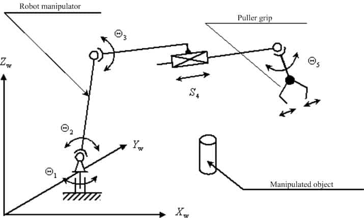
Figure 3 – Kinematic diagram of the robot manipulator
The manipulator, in its functional purpose, must ensure the movement of the manipulation object in space along a given trajectory and with a given orientation. To fully implement this requirement, the basic mechanism of the manipulator must have at least six degrees of freedom. However, manipulators with six degrees of freedom are complicated both in manufacturing and in operation, therefore in real constructions less than six degrees of mobility are used. The simplest manipulators have three, less often two, degrees of freedom, which makes the structure cheaper and simpler [9]. In the developed robotic manipulator Katana
5M180, four degrees of freedom will be realized that will provide movement along a given trajectory and will allow preserving the orientation of the object in space, but it will not greatly complicate the design.
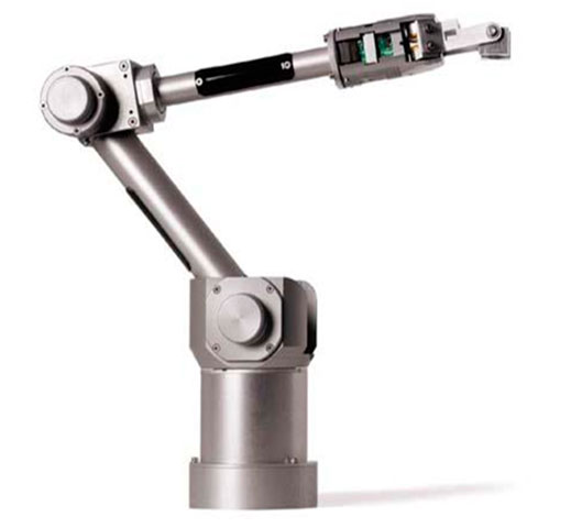
Figure 4 – Katana 5M180 robotic manipulator from Neuronics AG
4.2 Drive Selection
The main tasks of the manipulation robot are the positioning of the working element and the following of the given trajectory. Depending on the purpose of the manipulator, various types of drives are used to provide movement of the robot modules [7].
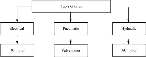
Figure 5 – Types of drives used in manipulators
Most of the currently existing manipulation robots are used to perform electric drive motions. Its main advantages with regard to pneumatic and hydraulic drives are:
- high efficiency;
- small size;
- convenience of management;
- wide power range.
In modern industrial manipulators, DC motors, stepper motors and valve motors are most often used. The most frequently used DC motors and valve motors [9].
This project uses DC motors with an integrated digital encoder, the company Maxon motor A-max, whose appearance is shown in Figure 5 [5].
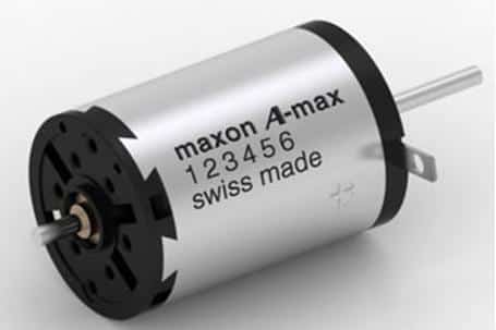
Figure 6 – Maxon DC motor A-max 22
The characteristics of the motor (at rated voltage) are shown in Table 1.
| Rated power, W | 6 |
| Rated voltage, V | 9 |
| Current without load, mA | 57,9 |
| Rated speed, rpm | 6530 |
| Rated current (maximum continuous current), А |
0.859 |
To transfer the necessary moment to the links of the manipulator, to create a power sensation, it is necessary to use a reducer. For this purpose, the reduction gearbox of the same Maxon motor company was chosen.
A reducing gear is necessary in cases where the rotational speed of the driven shaft of the machine is less than that of the motor. The task of the reducer is to reduce the angular velocity and increase the torque on the driven shaft.
Also, a digital encoder is used to measure the speed of the motors and obtain data on the position of the links of the manipulator.
4.3 Controller Selection
In order to control the manipulator drives, it is necessary to use a personal computer (PC) for calculating and generating a control program, as well as a microcontroller-based controller that must meet the requirements: [9]
- digital and analog input channels for sensors and peripherals;
- PWM resolution is less than 1 µs;
- serial interface UART/TTL (5 V);
- separate speed and acceleration control for each channel;
- high performance;
- hardware support for floating-point calculations.
For this system being developed, was chosen the microcontroller of STMicroelectronis STM32F4 [6].
The STM32F4 Discovery is designed to implement its own devices and applications using the hardware of the board.
The STM32F4 Discovery is equipped with:
- microcontroller STM32F407VGT6 with a Cortex-M4F core with a frequency of 168 MHz, 1 MB of Flash-memory, 192 Kb of RAM in the LQFP100 package;
- ST-Link/V2 debugger for debugging and programming MC;
- board power supply via USB or from external power supply 5 V;
- motion sensor ST MEMS LIS302DL and outputs of the digital accelerometer in three axes;
- sound sensor ST MEMS MP45DT02;
- Audio DAC CS43L22;
- eight LEDs: LD1 (red / green) for USB connection, LD2 (red) for 3.3V power supply, four user LEDs: LD3 (orange), LD4 (green), LD5 (red), LD6 (blue) and two LEDs for USB On-The-Go – LD7 (green) and LD8 (red);
- two buttons (for user programming and for restarting).
Thus, the debugger board is equipped with a large number of peripherals, which allows you to immediately implement on it examples of varying complexity.
References
- Зенкевич С. Л., Ющенко А. С. Основы управления манипуляционнымироботами. М.: Изд-во МГТУ им. Н. Э. Баумана – 2004. – 480 с.
- Юревич Е.И. Управление роботами и робототехническими системами.СПб. – 2001. – 168 с.
- Роботы-манипуляторы.рф [Электронный ресурс] – Режим доступа: http://роботы–манипуляторы.рф.
- В.В. Рябченко, Н.Н. Дацун, Программно-аппаратный комплекс управления роботами-манипуляторами фирмы NEURONICS AG [Электронный ресурс] – Режим доступа: http://ea.donntu.ru.
- Электродвигатели-редукторы.рф, Электронно-коммутируемый двигатель постоянного тока Maxon motor A-max 22, [Электронный ресурс] – Режим доступа: электродвигатели–редукторы.рф.
- Лабораторный практикум по изучению микроконтроллеров архитектуры ARM Cortex-M4 на базе отладочного модуля STM32F4 Discovery [Электронный ресурс] – Режим доступа: https://www.compel.ru.
- Конструкции промышленных роботов: Учеб. Пособие для СПТУ/ Е.М.Канаев, Ю.Г. Козырев, Б.И. Черпаков, В.И. Царенко. М.: Высш. шк., 1987. – 95 с.
- Варков А.А., Разработка и исследование системы управления манипуляционным промышленным роботом на базе контроллера, [Электронный ресурс] – Режим доступа: http://lib.eltech.ru.
- Н. Ю. Встовский, Е. А. Шеленок, Г. В. Шеразадишвили, Разработка учебного робота-манипулятора, аппаратная часть, [Электронный ресурс] – Режим доступа: http://pnu.edu.ru.
- Промышленный робот [Электронный ресурс] – Режим доступа: https://ru.wikipedia.org/wiki.