
Abstract
Content
- Introduction
- 1. Theme urgency
- 2. The aim and the tasks of the research, the planned result
- 3. A review of literary sources
- 3.1 Centrifugal pumps, their design, cha racteristics and energy indexes
- 3.2 frequency regulation of speed of electric drives of induction motors
- 3.3 Stand structure
- 3.4 Recommendations on energy saving
- References
Introduction
At present, the effective use of energy in general and electricity in particular is one of today's global economic problems. Energy saving (rationalization of energy production, distribution and use) in recent years has become one of the most important areas of technical policy in all countries. It should be noted that the use of the electric drive is one of many means of energy saving. The electric drive is the main consumer of electricity. It is about 80% of the electricity generated. The use of an asynchronous electric drive in machines and machines is about 75%. And this trend is constantly increasing. Such growth is caused on the one hand by the use of modern electrically conductive and insulating materials in the production of asynchronous motors, and it allows to increase its energy characteristics. thereby providing energy savings in traditional applications of asynchronous motors. And on the other hand, a jump at the modern level of the development of electronics ensures the manufacture of high-speed, reliable, inexpensive and easy-to-use frequency converters. Using an adjustable electric drive helps to save energy. And it means that the more precise the account of the features of the operation of the actuators, the better the work of the asynchronous motor itself.
1. Theme urgency
A very important point is the reduction of energy expense. It is especially true for large enterprises, where the expenses are mainly provided for the supply of electric motors. For example, such turbo mechanisms as pumps, fans, compressors, use about 25% of all generated electricity. It should be noted that little attention is paid to the creation of energy-efficient and economical operating modes of pumping units. Much of the electricity is used irrationally, with high expenses. The research of energy indexes and further reduction of expenses is an actual topic for today.
2. The aim and the tasks of the research, the planned result
The purpose of the Masters work is Research of the energy characteristics of a regulated electric drive for a pumping unit.
The tasks of the research:
- A review of literature on the design, characteristics and energy readings of centrifugal pumps.
- A review of the literature on frequency regulation of the speed of electric drives of induction motors.
- The creation of the structure and composition of the stand for the research of the energy readings of a centrifugal pump with a regulated electric drive.
- The fulfillment of experimental investigations on a laboratory stand.
- The creation of recommendations on improving the energy indexes of the frequency-controlled electric drive of centrifugal pumps.
3. A Review of Literary Sources
3.1 Centrifugal pumps, their design, cha racteristics and energy indexes
A centrifugal pump is a pump for pumping liquids in which the movement of the liquid and the necessary pressure are created by the centrifugal force arising from the action of the impeller blades on the liquid.
Centrifugal pumps are classified as follows:
- according to the number of steps (1 and 2-step);
- according to the number of inputs to the impeller (with 1 and 2-sided input);
- according to the location of the impeller relative to the bearing piers of the shaft (inter-bearing, cantilever);
- according to the location of the impeller axis (vertical and horizontal);
- according to the value of the coefficient of high-speed impeller (slow, normal, high-speed);
- according to the layout of the pump unit (separate, monoblock);
- according to the purposes (chemical, food, oil, condensate, etc.)
There are different kinds of pumps. The most common in the industry are centrifugal pumps. Their advantages are: uniformity of feed, high productivity, compactness, simplicity of the mechanism and speed due to the possibility of direct connection to the electric motor. It is also necessary to mention the possibility of manufacturing pumps from chemically resistant, difficult to mechanically processed materials. Advantages are also the possibility of pumping contaminated liquids and suspensions and installation on light foundations.The disadvantages of such pumps are relatively low developed pressure, as well as a strong influence of the network resistance on the productivity and efficiency of the pump.[1],[2]
Figure 1 – Graphical picture of a centrifugal pump [3]
(animation: 5 frames, 7 repetition cycles, 164 kilobytes)
The complex characteristic of a centrifugal pump is a combined graphical picture of the pressure head H, the power consumption N and the efficiency h of the total pump capacity Q at a constant or variable frequency of rotation of the impeller. A complex characteristic is given in Figure 2.
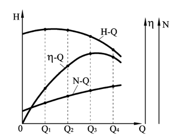
Figure 2 – Complex characteristic of a centrifugal pump
The most important characteristic is the interdependence of productivity and pressure. The theoretical characteristic of the flow ( head) is described by the equation of a straight line.
Where С adn Е - constant values, the values which depend on thefrequency of rotation, shape and dimensions of the impeller.
The position of the characteristic in the coordinates H – Q for the given values of the number of turns n, the outer diameter of the wheel D2 and the width of the channel at the exit from the wheel b2 depends on the blade angle at the exit β2. The characteristic H – Q is shown in Figure 3
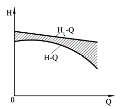
Figure 3 – The characteristic H – Q
Multiplying the left and right parts of expression (which is higher) by the value of the weighted second’s expenses, we obtain the equation of the theoretical power characteristic of the centrifugal pump:
Where Nt is the theoretical power; ρ – is the density of the pumped liquid Q – is the pump capacity.
Depending on the value of slope, the theoretical power characteristic graphically looks in the form of a straight line or a curve of the line emerging from the origin of the graph of N – Q. The characteristic is shown in Figure 4.
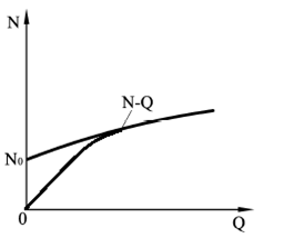
Figure 4 – The characteristic N – Q
Actual head (flow) differs from the theoretical one by the amount of losses in the flowing part of the machine. Therefore, the characteristic has a form that is different from the theoretical one, and the graph is below it.
The actual characteristic of the pump power can be obtained from the theoretical characteristics by summing (at given capacities) the theoretical power values and its losses. At the same time, the dependence of power on performance remains.
The main difference is that the actual power characteristics do not leave the origin because of power loss in the idle mode (Q = 0,N ≠0).
The efficiency of the pump is the ratio of the useful power Np to the consumed N:
Obviously, the total efficiency is zero for Q = 0 and H = 0, because for all operating modes of the pump is N ≠0. Between міх Q = 0 and Q = Q max the full efficiency reaches the maximum value. The characteristic η – Q is shown in Fig. 5
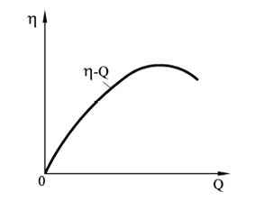
Figure 5 – Haracteristic η – Q
The operating mode of the pump, at which its efficiency reaches its maximum value, is called the optimal mode. According to the values of Q0 and Н0, H0 corresponding to the optimal regime, one can find the value of the speed coefficient ns, calculated by the formula:
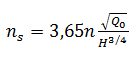
Where n – is the frequency of rotation of the impeller; Q0 – optimal performance; H0 – is the optimum head (flow).
The speed factor is a regime criterion similar to the fluid flow in pumps and plays an important role in their creation and application. lets consider the formula for the coefficient of speed of a centrifugal pump, designed to work with a given supply and pressure. The more speed , the greater the frequency of rotation, which is transmitted to its shaft. High frequency of rotation are advantageous because they make for the small size of the pump and the drive motor. Consequently, it is economically advantaeous to use high speed pumps.
At a specified frequency rotation , it is evident that the higher the speed coefficient, the greater the productivity and the lower the head. Therefore, pumps with a high speed factor are low-pressure and high-productive. [4]
3.2 Frequency regulation of speed of electric drives of induction motors
At present, frequency regulation of the angular speed of rotation of an electric drive with an induction motor is widely used. This makes it possible to smoothly change the rotational speed of the rotor in a wide range both above and below the nominal values.
Frequency converters are modern, high-tech devices. They have a large regulation range, and have an extensive set of functions for controlling asynchronous motors. The highest quality and reliability make it possible to apply them in various industries for controlling the drives of pumps, fans, conveyors, etc.
Frequency converters for voltage supply are divided into single-phase and three-phase, and the design of the electromechanical rotating and static. In electromachine converters, the variable frequency is obtained by using conventional or special electric machines. In static frequency converters, the change in the frequency of the supply current is obtained through the use of motionless electrical elements.
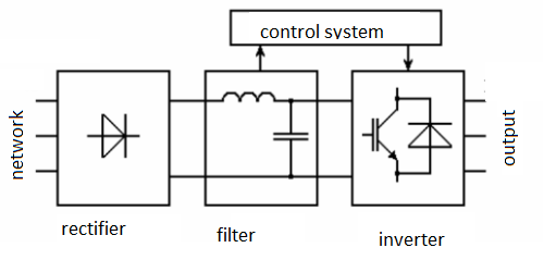
Figure 6 – Scheme of the frequency converter of an induction motor
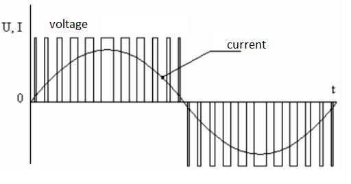
Figure 7 – The output signal of the frequency converter
Frequency converters for a single-phase network make it possible to provide an electric drive for production equipment with a power of up to 7.5 kW. A feature of the design of modern single-phase converters is that the input has one phase with a voltage of 220V, and at the output there are three phases with the same value of voltage. It allows you to connect three-phase motors to the device without the use of capacitors.
Frequency converters with a three-phase 380V power supply are available in the power range from 0.75 to 630 kW. Depending on the amount of power, the devices are manufactured in polymeric combined and metal housings. The most popular strategy for controlling asynchronous electric motors is vector control. Currently, most frequency converters implement vector control or even vector sensorless control (this direction occurs in frequency converters that initially implement scalar control and do not have terminals for connecting a speed sensor). Based on the type of load at the output, the frequency converters are divided by type of execution:
- for the pump and fan drive;
- for general industrial electric drive;
- It is operated as part of electric motors that work with overload.
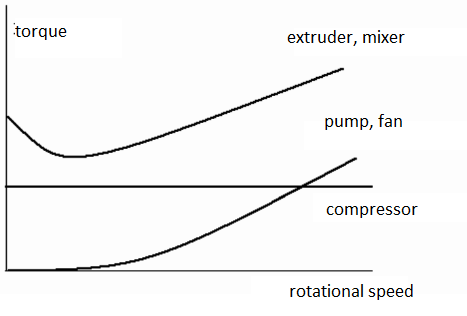
Figure 8 – Mechanical characteristics of typical loads
Modern frequency converters have a diverse set of functional features, for example, have manual and automatic control of the speed and direction of rotation of the engine, as well as an integrated potentiometer on the control panel. Provided with the ability to adjust the output frequency range from 0 to 800 Hz.
Converters are able to perform automatic control of an asynchronous motor by signals from peripheral sensors and drive an electric drive according to a given time algorithm. They support the functions of automatic restoration of the operating mode with a short-time power interruption. They perform transient control from a remote control and protect the motors from overloads.
From the equation ω0 = 2πf1/p we obtain the relation between the angular velocity of rotation and the frequency of the supply current.
If the voltage of the power supply U1 remains unchanged and the frequency changes, the magnetic flux of the induction motor changes. At the same time, for better use of the magnetic system, when the supply frequency decreases, the voltage must be proportionally reduced, otherwise the magnetizing current and losses in the steel will be greatly increased.
Similarly, as the power frequency increases, the voltage should be proportionally increased in order to keep the magnetic flux constant, otherwise (at a constant torque on the shaft), this will lead to an increase in the rotor current, overload of its current windings, and a decrease in the maximum torque.The rational law of voltage regulation depends on the nature of the moment of resistance.
At a constant moment of the static load (Mс = const) the voltage should be regulated in proportion to its frequency U1/f1 = const. For the fan load, the relationship takes the form U1/f²1 = const.
At the moment of loading, inversely proportional to the speed U1/√f1 = const.
The following figures show a simplified wiring diagram and the mechanical characteristics of an asynchronous motor with frequency regulation of the angular velocity.
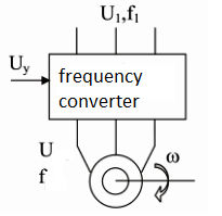
Figure 9 – Scheme for connecting a frequency converter to an asynchronous electric motor
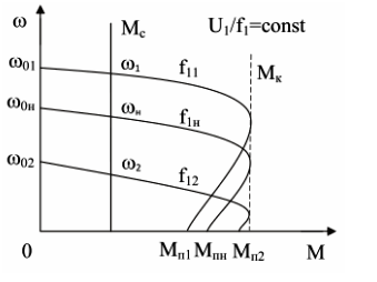
Figure 10 – Characteristics for a load with a constant static resistance moment
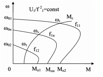
Figure 11 – Characteristics for a fan load
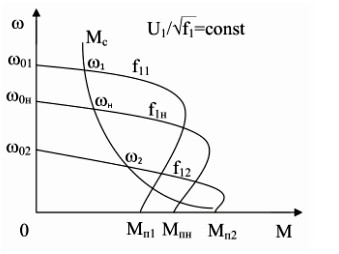
Figure 12 – The characteristics at the static moment of loading are inversely proportional to the angular velocity of rotation
Frequency control of the speed of an asynchronous motor allows to change the angular speed of rotation in the range of 20 ... 30 to 1. Asynchronous motor speed control downwards from the main one is carried out practically to zero.
When changing the frequency of the supply network, the upper limit of the speed of the asynchronous motor depends on its mechanical properties, especially since at higher frequencies the induction motor works with better energy indices than at lower frequencies. Therefore, if a reducer is used in the drive system, this frequency control of the motor should be carried out not only downwards, but also upwards from the nominal point, up to the maximum rotational speed permissible according to the mechanical strength conditions of the rotor.
The frequency method is the most promising for the regulation of an induction motor with a squirrel cage rotor. Power losses with such regulation are small, since they are not accompanied by an increase in slip.[5]
3.3 Stand Structure
The stand consists of the following components: tank 125liters_,Electropump centrifugal CP 130. (Rated frequency rotation nН =2900 rpm).
Transformer TR60 (step-down transformer) – transformer with shrink plastic housing, housing - shockproof, non-combustible thermoplastic of gray color. Mounted on a 35 mm DIN rail. The transformer is double insulated and does not require protective earthing. The secondary winding of the transformers is protected by two fuses. [6]
The Altivar 312 frequency converter [7] is designed to control asynchronous motors from 0.18 to 15 kW. It is reliable and compact, easy to put into operation. The Altivar 312 has functions suitable for the most frequent applications, in particular: transport equipment (small conveyors, electric, etc.); packing and packing equipment; Special mechanisms (mixers, mixers, textile machines, etc.); pumps, compressors and fans. Figure 13 shows the Altivar 312 frequency converter.
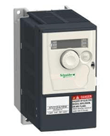
Figure 13 – Variable frequency drive Altivar 312
Altivar 21 – Altivar 21 is a frequency converter for controlling asynchronous electric motors at a power from 0.75 kW to 75 kW. It is specially designed for the most common applications in the buildings of the service sector: heating, ventilation, air conditioning and pumps. Thanks Altivar 212, energy savings of up to 70% [8]. Figure 14 shows the Altivar 212 frequency converter.
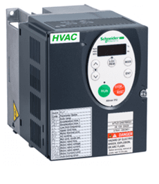
Figure 14 – The Altivar 212 frequency converter
The booth equipment includes contactors, an electromechanical valve, automatic switches, an AC-DC network converter, a pressure sensor, a set-up field, a panel for organizing the organization of stands, a Start button and a STOP button. According to safety rules, the stop
button is made oin the form of mushroom and of bright red color.The front panel includes: switches; warning lamps; package switch ATV 212 / ATV 312; terminals for connection.
3.4 Recommendations on energy saving
The process of regulation is complicated by the mismatch between the characteristics of centrifugal pumps and pipelines.In order to apply increased water flow through the pipeline, the head of the pumping station must be increased, and the characteristics of the centrifugal pumps are such that when the water supply increases, the head developed by the pump falls.At the same time, when the water supply decreases, the head of the pump should also be reduced, but it increases. Therefore, during periods of reduced water consumption, water supply systems are operated with excessive head pressure, which is extinguished in throttling devices or in the water fittings at the consumer. At the same time, the energy consumed by the pumps is spent irrationally on the creation of excessive heads, which, under the influence of which, leaks and unproductive water costs increase, and there are increased mechanical stresses in the walls of the pipes. Similar phenomena occur in heating, irrigation and other systems. The mismatch in the operating modes of pumps and pipelines can be eliminated by varying the pump speed, which must be adjusted in accordance with changes in water consumption or sewage inflow. When the pump speed is reduced, its water supply and the pressure developed by it decrease. With increasing speed, the head increases at the same time as the water supply increases. By adjusting the pump speed, its operating parameters are adjusted in accordance with the operating mode of the serviced system.To change the pump speed, an adjustable electric drive is required. The value of the speed of the pump with which it must operate at one time or another is determined by the system of the pumping unit ACS. The required speed is set depending on many factors. These include: the fluid flow in the system, its level in the tanks, the values of the static and dynamic back pressure, the number of pumps and pumping units running in parallel, supplying liquid to the system, and so on. At the time of writing this essay, the master's work is not yet complete. Approximate date of completion of the master's work: June 2018. The full text of the work and materials on the topic can be obtained from the author or his supervisor after the specified date.
At the time of writing this abstract of master's work is not yet complete. The estimated date of completion of the master's work: June 2018. The full text of work and materials on the topic can be obtained from the author or his adviser after that date.
References
- Центробежный насос // Википедия. – Режим доступа: "https://ru.wikipedia.org/wik...".
- Разинов А.И. Гидромеханические и теплообменные процессы и аппараты химической технологии: учебное пособие /А.И. Разинов, О.В. Маминов, Г.С. Дьяконов. – Казань: изд-воКГТУ, 2007. – 212с.: ил.
- Центробежный насос – схема и принцип работы устройства // Moikolodets – Режим доступа: "https://moikolodets.ru/centrobezhnyj-nasos-shema-368".
- Черкасский В.М. Насосы, вентиляторы, компрессоры: Учебник для теплоэнергетических специальностей вузов. – М.: Энергоатомиздат, 1984.-416 с.: ил.
- Частотное регулирование асинхронного двигателя // Школа для электрика. – Режим доступа: "http://electri...".
- Иванов Г.М., Онищенко Г.Б. Автоматизированный электропривод в химической промышленности. М.: Машиностроение, 1975.-312 с.:ил.
- Altivar 312. Преобразователи частоты для асинхронных двигателей. Руководство по установке. Schneider Electric 01/2010.
- Altivar 21 Привод с регулируемой частотой вращения для асинхронных электродвигателей. Краткое руководство.