
Abstract
Content
- Introduction
- 1 Theme urgency
- 2 Goal and tasks of the research
- 3 Investigation of drying pasty materials
- 3.1 Hardware design of drying pasty materials on the example of the Donetsk chemical reagents plant
- 3.2 Principle of calculation of the heat pump system
- 3.3 Heat pump selection and feasibility study
- Conclusion
- References
Introduction
Increasing the efficiency of using fuel and energy resources and creating the necessary conditions for transferring the country's economy to an energy-saving development path is one of the priority tasks of the Energy Strategy of Russia until 2020. [1]
1 Theme urgency
Secondary (by-side) energy resources (SER) are energy carriers formed during production that can be reused to generate energy outside the main production process. The relevance of the study is justified by world trends in increasing the efficiency of the use of fuel and energy resources and creating the necessary conditions for the transfer of the country's economy to an energy-saving development path [2].
2 Goal and tasks of the research
The purpose of the work is to develop a method of implementation, formed during the drying of pasty materials, secondary energy resources.
The tasks to be accomplished to achieve this goal:
- - analysis of existing developments on the problem;
- - Description of the working plant for drying pasty materials;
- - identification of the type of SER and its characteristics;
- - proposal for the implementation of SER;
- - feasibility study of technical solutions.
Object of investigation: drying process of pasty materials.
The subject of the research: instrumental design of the process of vacuum drying zinc bicarbonate.
Scientific novelty of the work is to develop a justification for the hardware design of the drying process of pasty materials, which causes the use of the SER process.
The practical importance of the work consists in using the results of the work to reduce energy and material consumption in making design decisions and the industrial introduction of heat pump plants for the use of SER.
3 Investigation of drying pasty materials
3.1 Hardware design of drying pasty materials on the example of the Donetsk chemical reagents plant
The schematic diagram of the apparatus design of the plant for drying pasty materials after modernization is shown in Figure 1.
Figure 1 — Diagram of the hardware design of the plant for drying pasty materials after modernization
animation: 16 frames, 10 repetition cycles, 126 kilobytes
The process of drying pastes after upgrading the hardware design is as follows:
The drying vapors from the working cavity of the dryer body 1 are supplied to the wet-type centrifugal-inertional apparatus 4 to be cleaned from the product dust to be carried away and then to the annular space of the heat pump evaporator 5, in which the heat of the drying vapor is withdrawn by the refrigerant boiling in the evaporator tubes. When cooling the drying vapors, the moisture condenses and the air is evacuated by a vacuum pump.
In the annular space of the evaporator 5, almost complete condensation of the drying vapors occurs, which eliminates the need to install a barometric condenser in front of the vacuum pump.
Sludge from apparatus 4 (water with dissolved product dust) and condensate of drying vapors from the evaporator 5 flow into the collection 9, whence the pump 10 is sent to the mother liquor collector and then to the reactor for the production of the product.
The vapor of the boiling refrigerant is sucked from the evaporator 5 by the compressor 6, compressed, while heating, and directed to the tube space of the condenser 7, where they are cooled to the condensation temperature by chemically purified water passing through the shell space. The heated chemically purified water leaving the condenser 7 is used to produce steam.
The liquid refrigerant from the condenser 7 passes the capillary reduction valve 8 and is sent to the tubes of the evaporator 5. After the valve 8, the liquid refrigerant pressure drops sharply, which leads to its boiling in the evaporator tubes due to the heat of the drying vapors.
Thus, the modernization of the hardware design of the drying process of paste-like materials in a vacuum-roller dryer allows the heat pump to transfer heat from the evaporating condenser 5 condensing in the intertubular space to chemically purified water passing through the annular space of the condenser 7 [3].
3.2 Principle of calculation of the heat pump system
SER, as already noted above, which is proposed to use — a pair of drying from the working cavity of the hull. To analyze the operation of the heat pump, T, S- and p, h-diagrams are used (Figures 2, 3).
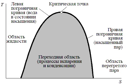
Figure 2 — T, S-diagram
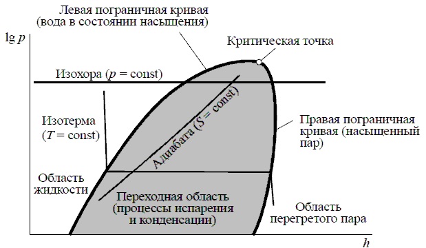
Figure 3 — p, h-diagram
The heat pump is a thermal machine in which external work is expended on the transfer of heat.
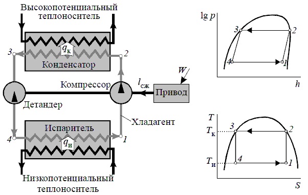
Figure 4 — The ideal heat pump Carnot's cycle:
qu — is the heat released by the low-potential heat carrier and obtained by the coolant during its evaporation; qk — is the heat released by the refrigerant during its condensation and obtained by a high-potential heat carrier; lсж — work, necessary for compression of a coolant; W — is the energy supplied to the drive; Tи and Tк — are the evaporation and condensation temperatures
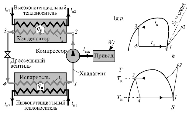
Figure 5 — Diagram and cycle of a steam compression heat pump
tв1, tв2, tн1, tн2 — temperatures of high-potential and low-potential coolant at the input and output
- Process 1-2 is an irreversible polytropic process of compressing refrigerant vapor in the compressor.
- Process 2-3 is isothermal condensation of the refrigerant in the condenser and return of heat to the high-potential heat carrier.
- Process 3-4 is an irreversible adiabatic expansion of the refrigerant in the throttle valve.
- Process 4-1 is the isothermal evaporation of the refrigerant in the evaporator due to the heat taken from the cold coolant.
The choice of the most optimal design of the heat pump requires a comparison of a variety of options for pump schemes, freons, the set temperature differences in heat exchangers. Calculation of heat pumps is traditionally carried out with the help of T, S or p, h — diagrams of working bodies (freons). The purpose of the thermodynamic calculation is to determine the efficiency indicators of the heat pump cycle. The procedure for calculating the heat pump cycles is proposed in the section.
The initial data for the calculation are:
— thermal load Qтн, kW, or low-grade heat-carrier flow Gн, kg/s;
— temperature of a low-grade coolant (cold water, antifreeze or brine) at the inlet to the heat pump tн1, ° C;
— temperature of a low-grade coolant (cold water, antifreeze or brine) after the heat pump tн2, ° C;
— temperature of high-potential heat carrier (hot water) at the entrance to the heat pump tв1, ° C;
— the temperature of hot water after the heat pump tв2, ° C [4].
3.3 Heat pump selection and feasibility study
We select a heat pump according to the following classification categories:
1) Principle of operation: a steam compression heat pump. In steam compression heat pumps, working bodies are selected that change their aggregate state at the necessary temperatures and pressures. They absorb heat on evaporation and give off under condensation. These processes form the isotherms of the cycle. The main component of the heat pump is a compressor that compresses steam. As working heat in these machines, chladones are used — mainly fluorochlorine containing hydrocarbons, the so-called "fluorochlorite" freons.
2) The source of low-potential heat: the heat of the process, viz. The drying vapors of pasty material.
3) Type of heat exchanger: water-air.
4) Principle of interaction of working environments: a closed cycle.
5) Mode of operation of the heat pump: monovalent [5].
6) Possible ways of using the heat selected by the installation: to maintain the climate of the factory premises (temperature, humidity), to the technological process, to heat liquids (water supply of the plant).
Technical and economic part of the question
The efficiency of the machines being designed consists primarily in the fact that their use ensures the economy of materials, fuel, electricity, labor of workers.
When designing a production reconstruction project, a calculation should be made:
- a) capital expenditures for equipment;
- b) operating costs;
- c) the payback period of new equipment.
When determining the cost of equipment, it is necessary to take into account the costs associated with its delivery, installation and other types of work [6].
Conclusion
When writing this essay, the master's work is not yet complete.
Final completion: June 2018.
The above stages of the study are the subject of more detailed study in the master's thesis in order to identify the most effective calculation and economic indicators.
The full text of the work and materials on the topic can be obtained from the author or his supervisor after the specified date.
References
- Методы и средства энерго- и ресурсосбережения. Версия 1.0 [Электронный ресурс] : электрон. учеб. пособие / В. В. Стафиевская, А. М. Велентеенко, В. А. Фролов. — Электрон. дан. (6 Мб). — Красноярск : ИПК СФУ, 2008.— (Методы и средства энерго- и ресурсосбережения : УМКД № 10-2007 / рук. творч.)
- Вторичные энергетические ресурсы (ВЭР) [Электронный ресурс]. — Режим доступа к статье: http://greenevolution.ru/enc/wiki/vtorichnye-energeticheskie-resursy-ver/.
- Солохин Д. М., Остапенко М. А. Энерго- и ресурсосберегающая модернизация аппаратурного оформления процесса сушки пастообразных материалов / Д. М. Солохин , М. А. Остапенко // Сборник научных работ «Комплексное использование природных ресурсов» — Донецк, ДонНТУ, 2015.— 172 с.
- Трубаев П. А., Гришко Б. М. Тепловые насосы: учеб. пособие / П. А. Трубаев, Б. М. Гришко. — Белгород: Изд-во БГТУ, 2010.— 143 с.
- Классификация тепловых насосов [Электронный ресурс]. — Режим доступа к статье: http://vantubo-service.ru/company/30-produktsiya/teplovye-nasosy/59-klassifikacziya-teplovyx-nasosov.
- Альперт Л. З. Основы проектирования химических установок: Учеб. пособие для учащихся химико-механич. спец. техникумов. — 4-е изд., перераб. и доп.— М.: Высш. шк., 1989.— 304 с.; ил.