
Casting steel on CCM is the main way of casting steel in modern metallurgical plants. This method significantly improves the quality and speed of casting, however, with the tightening of economic requirements, it becomes increasingly necessary to produce blanks that are the closest to the finished product by the dimensions. One of such directions is the creation of CCM for casting blanks over a large cross-section, at the moment it is known to use an installation with a mold width of more than three meters. In all modern continuous casting machines, a slag-forming mixture (SCO) is applied to the crystallizer, which prevents contact of the metal with oxygen, facilitates a more free passage of the formed metal crust through the crystallizer, and as a result, the surface quality of the workpiece.
Currently, at most CCMs, the SCO is fed manually, which leads to a higher consumption and a less even distribution of the mixture. In this regard, they implement a gradual transition to automatic submission of the SCO. In connection with this department, the MOHCM has designed a number of units for automatically feeding the SCO into molds of various sizes, one of which is the installation of the SCO feed into a particularly large crystallizer. When using this installation due to the automation of the SCO supply process, it is possible to provide uniform coating of the liquid metal with the slag-forming mixture, to reduce the consumption of the mixture, and to improve the quality of the casting blank.
In accordance with the classical view [2], the mechanism of interaction of the SCO with liquid steel in the crystallizer and with its walls is shown schematically in Fig. 1. As can be seen from the above diagram, some of the SCO, located directly on the metal mirror, melts and flows into the gap between the walls of the crystallizer and the solid crust of the ingot, acting as a lubricant.
To improve the process of sliding the hard crust along the surface of the crystallizer, as well as protecting the metal mirror from contact with the atmosphere and from heat loss by radiation, in the practice of continuous casting, special SCOs are applied, delivered in a certain amount to the surface of the metal in the crystallizer. And some of the SCO, which is located directly on the metal mirror, melts and flows into the gap between the crystallizer and the hard shell of steel, acting as a lubricant.
At the same time as the liquid steel is removed from the surface, due to its thermal action, three distinct layers are formed in the mixture: liquid, softened and sintered. According to the data of [2, 3], the liquid SCO layer performs the following main technological functions:
- reduces the heat output from the metal mirror in the crystallizer and prevents the formation of a hard crust on it;
- prevents secondary oxidation on contact metal mirrors with atmosphere;
- assimilates non-metallic inclusions floating into the slag;
- reduces frictional forces between the workpiece and the mold wall due to the presence of a liquid slag layer;
- increases the uniformity and allows you to adjust the intensity of the heat sink from the hard crust to the wall of the crystallizer;
- improves the quality of the surface of a continuously cast billet.
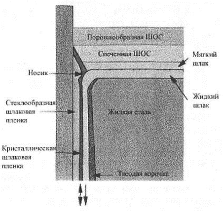
Figure 1 - Scheme of phase distribution in the crystallizer using the SCO
Therefore, the chemical composition, physical properties (particle size, temperature and melting rate) and the nature of the initial components that provide a complex of technological properties are the defining characteristics when developing mixtures for CCM crystallizers [4 ± 6].
The work of the mixture during the casting process determines the formation conditions and the parameters of the slag skull on the surface of the workpiece that affects the pulling force and also the intensity and uniformity of heat removal from the crust of the billet crystallizes to the walls of the mold, which in turn affects the surface quality of the billet [ 7 - 9].
When a liquid SCO flows into the gap between the surfaces of the workpiece and the crystallizer, a thin film is formed, consisting of:
- a layer of a glassy film, which will adhere to the walls of the crystallizer;
- a layer of a crystalline slag film located on a glassy film;
- a liquid layer adjacent to the surface of the workpiece.
The process of penetration of slag directly into the gap between the workpiece and the crystallizer and the formation of a slag layer in it is the most responsible in the SCO work, since this process actually determines the possibility of surface and subsurface defects in the workpiece, as well as the probability of metal breakthrough. At this stage, viscosity and slag hardening temperature ("crack temperature") play an important role, the surface tension at the slag-solid metal and slag-crystallizer boundaries, the value of the heat flow from the preform to the crystallizer, and the stability of the liquid slag from the surface of the molten metal through section of the meniscus [10, 11].
The results of the literature and patent searches conducted and their analysis made it possible to establish that the dispensed delivery of the slag-forming mixture to the crystallizer can be carried out by vibratory, pneumatic, mechanical and pneumomechanical methods. Any SCO dosing system essentially represents one of the combinations of the two mechanisms that implement the aforementioned methods of dosing and distribution of the mixture. Therefore, it is advisable to dwell in detail on those technical solutions that have found or can find industrial application.
One of the first devices for automatic metering of flux into the caster of the continuous casting machine for the casting of slabs with a section of 150x (1000-1200) mm was developed for the Donetsk Metallurgical Plant [1]. In this mechanical device (Fig. 2), the reciprocating motion of the crystallizer is used as a pulsed feed pulse.
As can be seen from the figure above, when using such a design of the metering system, the SCO feed is carried out into a local zone on the surface of the metal in the crystallizer, so that it is not possible to achieve an even distribution of the flux introduced throughout the melt, which is a significant drawback.
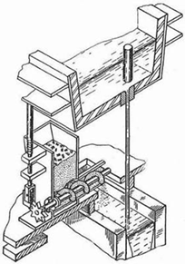
Figure 2 - Device for automatic dispensing of flux into the crystallizer
A similar principle of action is embedded in the design of the device, shown schematically in Fig. 3.
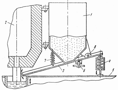
Figure 3 - Construction of the device for feeding the mixture into the CCM mold by means of a swinging inclined tray
To create a constant thickness in the crystallizer of the slag layer, it is proposed to feed the mixture from the hopper 1 suspended on the intermediate ladle 2 by means of a pivotally mounted chute 3 with a regulator 6. The tray, overcoming the resistance of the spring 7, can rotate about the axis 8 by transferring it the rear end by means of a spring follower 4 of the reciprocating motion of the mold plate 5 [12]. With such a constructive arrangement of the device, the amount of the mixture coming from the hopper depends on the deviation of the tray set by the regulator 6 and the oscillation frequency of the mold. It should be noted that, with the obvious simplicity of the mechanism for dosed mixture injection due to the absence of a special drive for its operation, this system can not be successfully used on a slab caster because of the limited metal surface area on which it allows the SCO to be fed into the crystallizer.
In order to eliminate the noted shortage in the device proposed by the specialists of the HCHI. Bardeen (Figure 4), including a permanently located bunker 1 connected to a pipe 2 mounted on rolling bearings 3 and 4 and having holes 5 with latches 6.
In this case, a screw 7 is passed through the pipe 2, the shaft 8 of which is mounted on the bearings 10 and is rotatable by the drive 9. The tube 2 is provided with a lever 11 connected to the pneumatic cylinder 12, as well as trays 13 and guides 14. During operation, the pipe 2 of the device is located parallel to the wide wall of the crystallizer 16. Upon rotation, the screw 7 moves the mixture through the pipe 2, whose openings 5 with the trays 13 are in the upper position. At the time of filling the pipe with the mixture to its full length, the pneumatic cylinder 12 acting on the lever 11 and turning the pipe 2 is turned on. The mixture is poured out of the tube and passes through the trays 13 to the metal meniscus where the slag layer 17 is formed. After the mixture is completely emptied from the tube 2, The pneumatic cylinder rotates to the starting position for the next filling of the material.
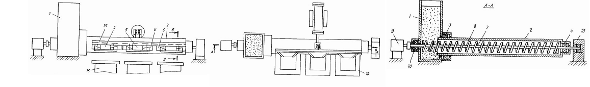
Figure 4 - Dosing system of the HCHI design. Bardine for the input of slag-forming mixtures into the continuous casting machine mold for casting billets of large cross-section
To control the amount of the mixture supplied, slides are used that move manually in the guides 14.
Additionally, the flow rate of the mixture can be adjusted by changing the speed of rotation of the pipe 2 during the casting process of steel [13]./It should be noted that this installation, which is located stationary on the work platform along the mold of the continuous casting machine, interferes with the trolley to move it to the reserve position after the casting has ended to perform maintenance of the intermediate bucket or to replace it.
In the device for feeding slag-forming mixtures to the crystallizer, patented by specialists of OAO Severstal (Figure 5), different
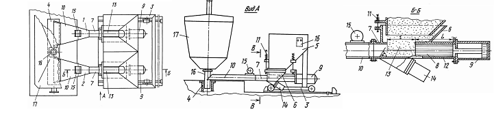
Figure 5 - Dosing system of the structure of JSC "Severstal"
side of the submerged nozzle 16 of the pouring device of the intermediate ladle 17, it is proposed to use two supply hoppers 6, each of which is rigidly connected to the dispenser 7 and movably by means of spring suspensions 11 to the receiving hopper 5. The dispenser is in the form of a housing with a channel for moving the piston 8, in action by the pneumatic cylinder 9. The dispenser housings are fixedly connected to the distributor 10 in the form of sockets provided with vibrators 15 and hanging over the crystallizer 4. The metering system is mounted on the trolley 3 mounted on the rails on the side of the side wall of the intermediate ladle.
The mass flow rate of the mixture to be fed to the crystallizer is determined by the cross section of the channel for moving the piston and its stroke [14]. The drawback of the system is that it clutters the work area, creating inconvenience to the dispenser, and is an obstacle in case of an emergency exit of the trolley with an intermediate bucket.
In another way, the system for dispensing a mixture protected by a US patent is arranged and operated (Figure 6). Uniform delivery of the mixture to the crystallizer is proposed to be performed by means of a mobile installation including a cart 8, on the platform 13 of which two screw feeders 11 are mounted adjacent to the bottom of the hopper 10 covered with a cover 9 with a metering hole 7. The rotation of the dispenser augers is carried out by means of geared motors 12 operated from the remote control 19. Each of the dispensers, by means of a two-cranked shaft 23 rotated by the motor 14 and the connecting rod 24, can oscillate in a horizontal plane in a sector limited viscous mold wall and the submerged nozzle 4. To straighten the path of movement of the mold walls of a relatively wide feed nozzles 18 mounted on the pipe ends of auger feeders for relative longitudinal movement on
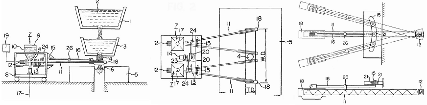
Figure 6 - The system of dosed supply of SCO to the crystallizer of slab CCM with the help of twin screw feeders
the platform 13 is provided with two profiled grooves 15 in which the rollers 21 are connected to the ends of the rods 16 fixed in the supports 26 and connected to the nozzles 18.
With such a kinematic scheme, during the functioning of the metering system, thanks to the addition of reciprocating (relative) and rocking (portable) movements of the nozzles, a uniform feeding of the mixture along the entire surface of the metal mirror in the crystallizer is provided [15].
A
significant disadvantage
of this system is that it clutters the
work platform near the intermediate ladle from the location of the
control levers of its stopping filling devices and is an obstacle
during the emergency exit of the trolley from the crystallizer.
Taking
into account the
fact that several slab machines for
continuous casting of blanks of superlarge cross-section are currently
operating abroad [10], when creating a metering system designed to work
in the production of ingots, the width and thickness of which exceed 2
and 0.3 m, respectively, was A constructive scheme has been adopted
(Figure 7), assuming the presence of two socks that feed the
slag-forming mixture separately to the metal mirror in the crystallizer
into zones delimited by the immersion glass. Moreover, each of the
socks makes movement simultaneously in two directions - along and
across the crystallizer. This makes it possible to increase the
uniformity of the distribution of the SCO throughout the free surface
of the steel in the crystallizer and to reduce the speed of movement of
the carriages on which the feeding socks are installed. The developed
system includes a rack 19 mounted on two swivel arms 15 and 22 along a
wide wall of the mold 20 and provided with two guides 17 and 18
supported by two pairs of rollers 10 two carriages 9 having a relative
longitudinal displacement of 0.4 - 0.45 of the slab width by means of a
drive consisting of a self-locking worm motor-reducer 13 with two shaft
ends of the output shaft arranged vertically. The lower shank by means
of a bevel gear 12 is connected to the pinion 11 meshed with the teeth
of the rail, and the upper shank is provided with a crank 5 which, by
means of a connecting rod 44. Review of research and
development
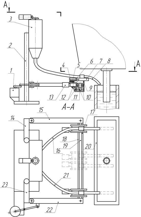
Figure 7 - The system of dosed supply of SCO to the crystallizer of slab CCM for casting blanks of super-large cross section
is
connected to the bar 6
bearing the feeding toe 8 and is able to
be transversely moved relative to the carriage, and hence the mold, in
two horizontal guides 7. Both feeding toes are connected by means of
flexible metal hoses 16 and 21 to the feeding hopper 3 fixedly fixed to
the two posts 2 , provided with brackets 14 and 23, which together with
the swivel arms 15, 22 and the rack 19 form a parallelogram mechanism,
so that the rack can drive a parallel-parallel movement A relatively
wide wall of the mold 20 for withdrawing from it to the parking
position. The dosed out delivery of the slag-forming mixture at the
same time with two spiral dispensers is carried out from one drive
including a geared motor with a regulated speed of the output shaft on
which a pinion is mounted, meshed with two gears rotating vertical
transmission shafts rigidly connected at their lower ends to the
spirals of flexible metal hoses .
Work of
the carriages of a
twin-screw machine
Figure 8
- Moving
carriages of distributing SCO along the
crystallizer
(animation: 111 kb, frames 15, number of repetition cycles
5, delay between frames 500 ms)conclusions
This
work has
not been completed yet, but at this stage it can be confidently said
that the development of an apparatus for a super-large cross-sectional
crystallizer will make it possible to convert existing CCMs of this
type to automatic supply of SCO, to significantly reduce the
consumption of the mixture, to improve the quality of the workpiece and
to reduce the wear of the walls of the crystallizer 1.
Дюдкин
Д. А. Качество
непрерывнолитой стальной
заготовки / Дюдкин
Д. А. – К.:
Техніка,
1988. – 253 с. 2.
Процессы непрерывной
разливки: Монография / [Смирнов А. Н. [и др.]. – Донецк:
ДонНТУ,
2002. – 536 с. 3.
Куклев
А. В. Практика
непрерывной разливки стали / А. В. Куклев, А. В. Лейтес. –
М.:
Металлургиздат,
2011. – 432 с. 4.
Производство
теплоизолирующих и шлакообразующих смесей для современных МНЛЗ / С. В.
Шлемко
[и др.] // «50 лет непрерывной разливке
стали в
Украине»: Сб. научн. тр. / под ред.
проф., д.т.н. Д. А.
Дюдкина, проф., д.т.н. А. Н. Смирнова. – Донецк: Изд-во
«Ноулидж» (донецкое
отделение), 2010. – С. 213 – 223. 5.
Комплексное
использование высокоосновных теплоизолирующих, шлакообразующих
рафинировочных и
разливочных смесей при высокоскоростной разливке на слябовой МНЛЗ
/ О.
Б. Исаев [и др.] //
Бюллетень научно-технической и экономической информации
«Черная
металлургия»
ОАО «Черметинформация». – 2007.
– №7. –
С. 25–31. 6.
Шлакообразующие смеси
ТСК для кристаллизатора МНЛЗ ЗАО «АзовЭлектроСталь»
/ М. А.
Шумаков [и др.] //
50 лет непрерывной разливке стали в Украине: науч.-техн. конф., 4-5
ноября 2010
г.: сб. науч. тр.
конф. – Донецк,
2010.
– С. 507–514. 7.
Механизм формирования
шероховатой поверхности шлакового гарнисажа и ее влияние на величину
термического сопротивления зазора между оболочкой слитка и стенкой
кристаллизатора УНРС / Н. П. Лякишев [и др.] // Металлы. –
2005.
– №3. – С.
3–15. 8.
Физико-химические
основы нового метода управления отводом тепла от слитка к
кристаллизатору А. И.
Зайцев [и др.] // Сталь. – 2003. – №3. –
С.
70–74. 9.
Зайцев
А. И.
Направления и методы создания шлакообразующих смесей для непрерывной
разливки
стали с высокими эксплуатационными и экологическими характеристиками /
А. И.
Зайцев, К. Б. Калмыков // Тр. IX конгресса сталеплавильщиков: Старый
Оскол,
17–19 октября 2006). – М., 2007. – С.
638–644. 10.
Дождиков В. И.
Комплексное исследование условий контакта непрерывного слитка со
стенками
кристаллизатора / В. И. Дождиков, И. И. Шеинфельд, В. Е. Бережанский //
Непрерывная разливка стали: сб. науч. тр. ЦНИИчермет. – М.:
Металлургия, –
1989. – С. 32 – 43. 11.
Смирнов А. Н.
Свойства шлакообразующих смесей для непрерывной разливки стали с
повышенной
скоростью / А. Н. Смирнов, С. Л. Макуров, М. В. Епишев, А. Ю. Цупрун //
Металл
и литье Украины. – 2006. 12.
А. с.
1764790 СССР,
МКИ3 В 22 D 11/10. Устройство для подачи шлакообразующей смеси в
кристаллизатор
/ Е. Н. Суханов, Ю. В. Сосин, А. Н. Лазинцев (СССР). – №
4474824/02; заявл.
18.08.88; опубл. 30.09.92, Бюл. № 36. – 3 с. 13.
А. с.
644594 СССР,
МКИ3 В 22 D 11/10. Устройство для подачи порошкообразных шлаковых
смесей в
кристаллизатор / В. И. Лебедев, Ю. Е. Кан, А. В. Лейтес, В. М. Паршин,
Г. Н.
Брикманис, К. П. Веселов (СССР). – № 2412718/22-02; заявл.
18.12.76; опубл.
30.01.79, Бюл. № 4. – 3 с. 14.
Пат.
2171157
Российская Федерация, МПК7 В 22 D 11/10. Устройство для подачи
шлакообразующих
смесей в кристаллизатор / Сандальнев Ю. А., Ведешкин В. В., Ордин В.
Г., Плешин
Ю. А.; заявитель и патентообладатель Открытое акционерное общество
«Северсталь». – №99114260/02; заявл. 29.06.1999;
опубл.
27.07.2001.
– 4 с. 15.
Пат.
4312399 The
United States, Int. Cl3 В
22 D 11/10. Flux powder
supplying apparatus for continuous casting /
Nishida
Shinji, Okayama; Ohtsuka Takashi, Bizen; Satoh Mitsukuni, Okayama;
Kashimoto
Satoru, Wake, all of Japan; Assignee Shinagawa Refractories Co., Ltd.,
Tokio,
Japan. – No.129383; filed 31.10.1979; published 26.01.1982.
– 7 p.Conclusions
References