
Abstract
Содержание
- Introduction
- 1. The purpose and objectives of the study
- 2. Analysis of design features of systems for quick change of dosing and submersible stands
- 3. Development of the improved device dosing and submersible drawings
- 3.1 Study of energosile parameters systems of quick change of dosing and submersible washers
- 3.2 Mathematical modeling of thermal stresses in refractory elements of the device for fast replacement of washers – dosers load caster
- Conclusion
- References
Introduction
Modern metallurgical production requires a constant increase in the efficiency of systems for the rapid change of metering and submerged glasses in the continuous casting process by long and extra-long series on the continuous casting machine. The main requirements for such systems are: reliability of operation in conditions of long exposure to high temperatures; the ability of the structure to withstand significant loads, while performing technological operations; ease of maintenance and operation.
1. The purpose and objectives of the study
The purpose of this study is to develop and substantiate the design and energy-power parameters of a rapid change of metering and immersion nozzles system, which would eliminate the heavy physical labor of CCM personnel, reduce the time spent for the operation, minimize energy costs for its implementation and rationally use, site.
To achieve this goal, it is necessary to solve the following tasks:
1. On the basis of a comparative analysis of existing technical solutions, to develop an improved complex system for rapid change of metering and immersion refractory cups.
2. Develop a methodology for calculating the kinematic and energy-power parameters of the proposed system.
3. Carry out a verification of the correctness of the technical decisions and the calculated dependencies on the physical analogue of the proposed system.
4. Issue recommendations for industrial use of the proposed development.
5. To evaluate the technical and economic efficiency of the developed technical solutions.
Analysis of design features of systems for quick change of dosing and submersible stands
The most widely used at metallurgical enterprises are devices of firms: INTERSTOP, VESUVIUS and IFGL, the construction schemes of which are shown in Fig. 13.
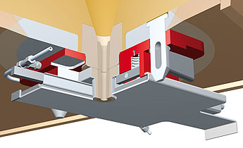
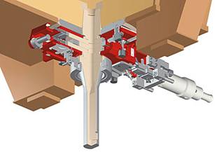
Figure 1 – The INTERSTOP system
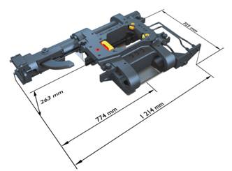
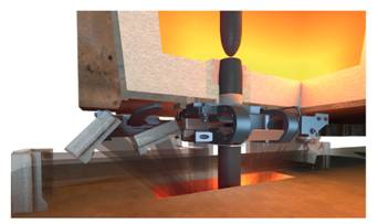
Figure 2 – The system of the company VESUVIUS
One of the main drawbacks in these systems is the complexity of the design solutions in the development and maintenance of the pressure-holding unit of the dispensing nozzle to the upper base refractory block. The design requires careful selection of all installed springs to ensure the same elastic characteristics, as well as their regular monitoring.
The analysis of the possibility of performing the adjustment and maintenance operations that the systems developed by INTERSTOP and VESUVIUS (Fig. 1, Fig. 2), the control of the elastic force developed by each spring, and its replacement in the event of failure are possible only after removing the entire device From the bucket and complete disassembly at the stand in the workshop.The system proposed by IFGL (Fig. 3) allows to check the elastic characteristics of the springs directly on the ladle, however, a partial disassembly of the pressing unit of the replaceable refractory element is required to replace them.
Experience in the operation of such devices has shown that the performance indicators for their use differ significantly. The main reason for this is the absence in the technical literature of techniques for calculating and optimizing the working parameters of the filling systems of this class, which in turn leads to the destruction of the replaceable metering element.
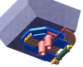
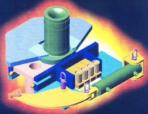
Figure 3 – IFGL system
3.Development of the improved device dosing and submersible drawings
As a result of the analysis of advantages and disadvantages of existing devices, as well as on the basis of the results of laboratory studies and mathematical modeling of the stress-strain state of structural elements, the staff of the department "Mechanical equipment of ferrous metallurgy plants named after professor Sedush VY" DonNTU proposed a new device design for rapid replacement of the beaker-dosers in Fig. 4 [1].
The device consists of a metal casing 3 which is fixed to the outer surface of the bottom of the intermediate ladle by screws 4. In the casing 3 there is placed a refractory nest box with a steel drain pan 1 of the intermediate ladle. In the case 3 there is placed a replaceable refractory beaker 12 which can be moved by a removable power hydrocylinder 5. Pressing of the dispenser cup to the nest block is carried out by a mechanism including rotary elements 11 mounted on the axes 10 on both sides of the dispenser 12. To transfer the pressing force to the dispensing bowl 12, the rotary members 11 are kinematically interconnected with the springs 8 arranged on the guide rods 9 in the horizontal cylindrical channels made in the metal housing of the unit 6. On the internal surfaces of these channels, the thread for screwing the plugs 7 is cut. on the outgoing end part there is either a slot for a screwdriver or a key for a key.
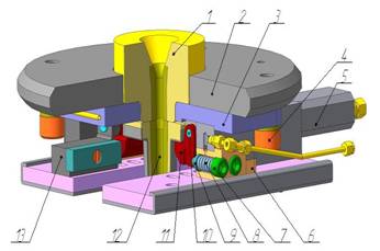
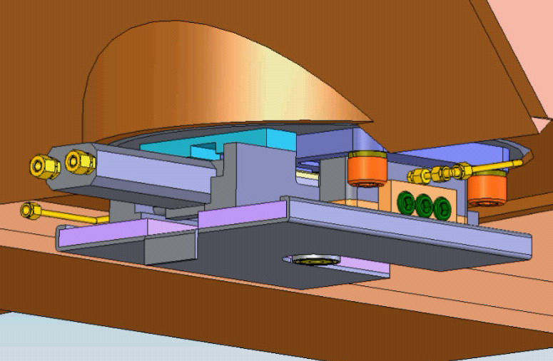
Figure 4 – DonNTU system
During the metered overflow of steel from the intermediate ladle to the molds of the continuous casting machine, if a replacement cupboard has to be replaced with a spare one, a hydraulic drive is actuated, the power cylinder of which pushes the metering elements to the calculated distance, as a result of which the new refractory product takes the place of the spent one.
Due to the improvement in the design of the supporting assembly of the casting system, there is no need for its complete disassembly when controlling the force developed by each of the springs or in the event of their replacement. In addition, it was possible to extend the permissible limits of the deviation of the rigidity of the elastic elements from the set value, since the proposed design allows individual adjustment of the force of the spring action on the dispensing cup without removing the filling device from the ladle.
When servicing the filling system to control the spring stiffness, the tailpiece of the torque wrench is alternately inserted into the hole of each of the rotary elements, and, by rotating the element on the axis to a small angle, determine the elastic force provided by the spring as shown in Fig. 5. If this force deviates from the set value, it is necessary to turn the plug in the desired direction, compressing or loosening the spring. If, after such adjustment, still fails to achieve the desired result, the spring that has become unusable is replaced by a new one, by screwing the plug completely out of the threaded socket [2].
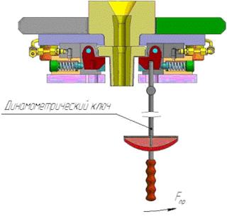
Figure 5 – The control scheme of the elastic force developed by the node spring pressing the beaker glass
Due to its design features, the proposed device is much easier to maintain and operate in comparison with the known foreign analogs, since it allows to control and regulate the force developed by each of the springs, to replace them, if necessary, without removing the filling system from the bucket and carrying out its full or partial disassembly. In addition, this device has a universal design and can be transformed to provide a quick replacement of the immersion nozzles used to protect the steel from secondary oxidation in the area of the intermediate ladle - the crystallizer of slab CCM.
3.1 Study of energosile parameters systems of quick change of dosing and submersible washers
These devices in the design are identical to the two-slab slide gate, however, it is not possible to use the dependences obtained for gate type gate valves [3] to calculate the force characteristics of their drives, since the high-speed operation modes of these filling systems are practically incommensurable. With the same working stroke of moving parts in both systems, 120-130 mm, the duration of their movement from one extreme position to another differ by an order of magnitude, since the shutter plate makes a full stroke in 3-7 seconds, and the dispensing glass - in 0, 3 - 0.5 seconds.
A sharp increase in the speed of the spent and backup beaker-dispensers in the initial stage of the process of their change, provided by the hydraulic drive, entails the development of dynamic loads acting on the elements of the design of the dispensing device. Establishing and taking into account the nature of the change in the static and inertial forces overcome by the drive will allow us to justify and optimize the values of its energy-power parameters, which ultimately will contribute to improving the reliability and economy of the entire propulsion system and developing the theoretical bases for its calculation [4].
The goal can be achieved only based on the known methods for solving the problems of drive dynamics of hydromechanical systems used in metallurgy [5, 6] and supplementing them with new provisions developed taking into account the specifics of the operation of the dosed steel overflow devices from the intermediate caster. Given the extreme conditions of operation of the steel-pouring equipment and the associated difficulties in using test and measuring facilities to obtain data on the force loading of the full-scale sample during the operation to replace the failed refractory element, the required information on the significance and nature of the increase in the forces of technological resistance was established on the basis of the results of the special experimental studies. For their carrying out, a physical analogue of the system for rapid change of the intermediate-bucket dosing bucket for a continuous casting machine was designed and manufactured (Fig. 6), which in a constructive and scale-like manner corresponded to the actual sample and differed only in the method of providing the pressing force of the replaceable refractory element. The controlled force of action on the bearing surface of its metal clips was developed with the help of a set of loads hung on two levers.Due to the change in the mass of loads and the length of the levers, they achieved strict fixation in a wide range of values of the pressing force of the dispensing glass, which made it possible to improve the accuracy of the measurements.
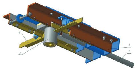
Figure 6 – The physical analog of an industrial device for fast replacement of cups-batchers
3.2 Mathematical modeling of thermal stresses in refractory elements of the device for fast replacement of washers – dosers load caster
The most thermally loaded structural element is a beaker-dispenser, therefore at the first stage of the research it was decided to consider the distribution of temperatures in it. The dispenser glass is an element consisting of a metal casing, medium refractory part and zirconium insert, the materials of which have different thermal properties. Considering the length of the process of clearing a long series, the stationary problem of heat conduction was considered in the course of modeling. In this case, the temperature field of the cup is described by the equation of thermal conductivity:
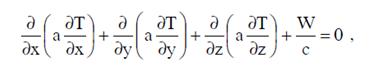
where a is the thermal diffusivity coefficient reflecting the heat-inertial properties at the considered point of the dispenser glass; a = ? / c;
c, л is the volume heat capacity and the coefficient of thermal conductivity of the glass materials;
T - temperature at the considered point of the dispenser glass;
x, y, z are the coordinates of the point under consideration;
W is the power of the heat source.
The temperature effect on the glass is a jet of liquid steel passing through the channel, as well as the radiation of a mirror of the metal in the crystallizer.In view of the complex spatial construction of the glass, the solution of the problem was carried out using the ANSYS application package, the realizing finite element method [7]. Since the beaker is an axisymmetric element, a geometric model corresponding to a quarter of the glass was created for the calculation (Fig. 7a). As boundary conditions, the following were used: on the surface of the steel-casting channel - convective heat transfer from liquid steel with a temperature of 1600 ° C (heat transfer coefficient 0.27 MW / (m2 • K) [8]); on the bottom surface of the cylindrical part - heat transfer by radiation with a heat flux density of 20 kW / m2 [8]; on the outer surface of the glass casing - convective heat transfer to the environment (air temperature is assumed to be 30 ° C). In the course of the simulation, two variants (No. 1 and No. 2) of the construction of the dispenser glass, differing in the height of the casing flange, were considered. In this case, the finite element models (Fig. 7b) consisted of 33775 and 33499 elements respectively.
As a result of the performed calculations, the distribution of the temperature fields in the construction of the dispenser glass was obtained (Fig. 8).As you can see, the zirconium insert has the highest temperature, then in the middle part there is an intensive drop in temperature. The temperature of the casing is in the range of 60 ... 250 ° C.
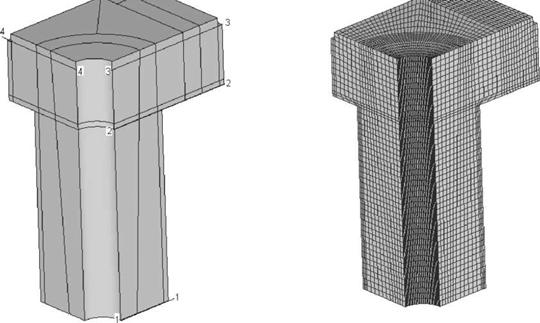
Figure 7 – The geometric model (a) and the finite element model (b) of the stack-on-batcher (1, 2, 3, 4 characteristic cross-sections)
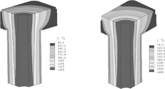
Figure 8 – Patterns of distribution of temperature fields in a glass-batcher:a) option number 1; b) option number 2
Graphs of temperature changes along individual sections are shown in Fig. It should be noted that in general, the distribution of temperature fields is similar for both versions of the glass construction, but for option No. 2 (with a short side of the casing), the jacket temperature is 10-17 ° C higher.
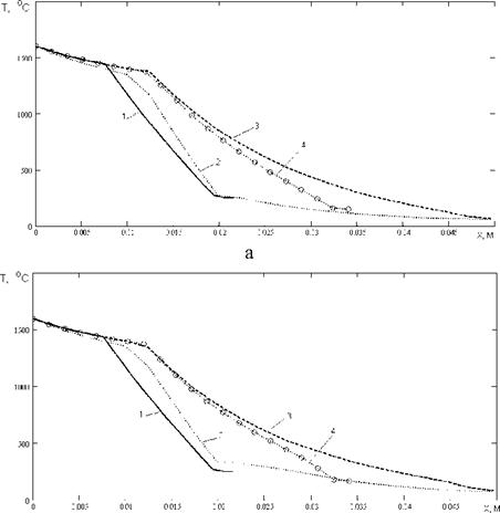
Figure 9 – Change in temperature in the characteristic sections of the dispenser glass (1, 2, 3, 4 - characteristic cross-sections): a) option number 1; b) option number 2
Under the influence of temperature fields, thermal stresses arise in the construction of the dispenser glass, which are described by the Dugamel-Neumann relationships [9]:
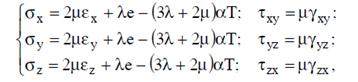
where Єx, Єy, Єz are the normal stresses along the x, y axis, respectively;
Тху, Туz, Тzх are tangential stresses;
Ех, Еу, Еz - relative linear deformations along the x, y axis, respectively;
Уxy, Уyz, and Уzx are the relative angular deformations;
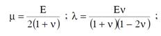
л, у are Lame coefficients that depend on the Poisson coefficient у and the elastic modulus E of the beaker materials:
формула– Change in temperature in the characteristic sections of the dispenser glass (1, 2, 3, 4 - characteristic cross-sections): a) option number 1; b) option number 2
e is the volume deformation: e = Еx + Еy + Еz;
? - coefficient of linear expansion of the materials of the dispenser;
T is the temperature at the considered point of the structure.
The problem of the stress-strain state of the dispensing glass caused by temperature effects was also solved with the ANSYS package. In this case, the temperatures used for each node of the finite element models were used as the load, and the movement restrictions were set on the top surface of the dispensing bowl, which is the contact point with the base refractory plate located in the flange of the bottom of the intermediate ladle. As a result of the calculation, the distribution of stresses in the body of the beaker was obtained (Fig. 10).
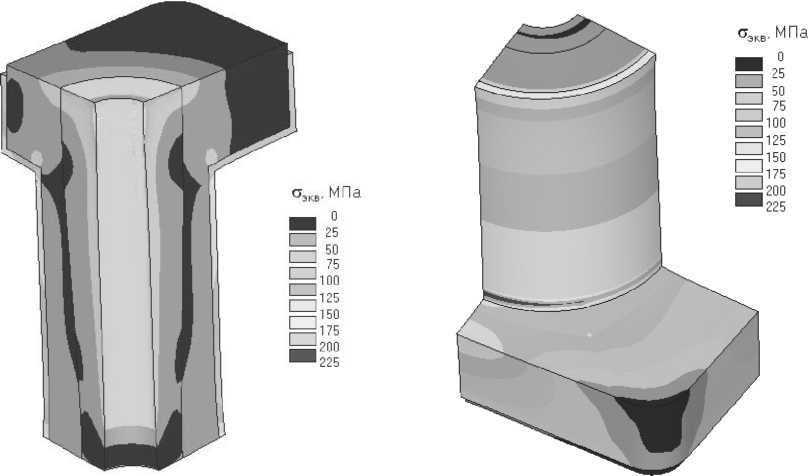
Figure 10 – Pictures of the distribution of equivalent stresses in a dispensing bowl 2
It is established that the maximum equivalent stresses in the fire-resistant parts of the glass do not exceed 37 MPa, and in the metal casing 210 MPa, which is below the permissible values of 52 MPa and 240 MPa. For the construction of a glass with a short bead (option No. 2), the voltage in the whole is 5..10% higher. The maximum stresses occur on the surface of the dispenser glass facing the metal mirror in the crystallizer, as well as on the casing at the junction of the cylindrical and flat parts. The maximum linear deformations in the direction of the x and y axes (expansion of the structure) reach 1 mm, and in the direction of the z axis (elongation of the structure) do not exceed 2 mm. The calculated values of the deformations of the refractory element were taken into account when assigning structural dimensions and guaranteed clearances in the supporting and guiding nodes of the mechanical system of the experimental design of the developed casting device [9].
Conclusion
As a result of the analysis of the merits and demerits of existing fast glasses changing systems, as well as on the basis of practical and laboratory tests, a new version of the quick-change system of dispensing glasses was developed. The use of the proposed device will simplify its maintenance and operation in comparison with known foreign analogues.
When writing this essay, the master's work is not yet complete. Final completion: June 2018. The full text of the work and materials on the topic can be obtained from the author or the head after the indicated date.
References
- Pat. 74507 Ukraine, В 22 В 41/56. Device for changing the dosing cups of the intermediate ladle of the continuous casting machine. Opubl. 15.12.2005. Bul. № 12.
- Perfection of the design of the device for rapid change of tumblers-troughs of tundish CCM / SP. Eronko, A.N. Smirnov, D.A. Yakovlev et al. // Metallurgical and mining industry.-2006.m. №8.- P. 107-109.
- Eronko SP Calculation of energy-force parameters of bucket gates // Metallurgical and mining industry. - 2007. - No. 3. - P. 104-108.
- VI Bol'shakov, "Investigation of dynamic loads of metallurgical machines," Zahist metallurgicheskih machines for breakdowns. Intervuzivsky thematic zbirnik scientifically prac. - Mariupol: PDTU, 1999. - P. 6-14.
- Kozhevnikov SN, Peshat VF Hydraulic and pneumatic drives of metallurgical machines. - M .: Mechanical Engineering, 1977. - 310 p.
- Holidays AV Hydraulic drive in metallurgy. - Moscow: Metallurgy, 1973. - 336 p
- Kaplun AB, Morozov EM, Olfereva MA ANSYS is in the hands of an engineer. - M .: Editorial URSS, 2003. - 272 p.
- Ogurtsov AP, Zhulkovskaya II, Kulik AD Calculation of the Temperature State of the Bucket Slide Gate with Various Methods of Casting Steel // Izv. universities. Ferrous metallurgy. - 2001. - №4. - С.11-15.
- The device for fast replacement of the cups-metering devices of the intermediate ladle of the continuous casting machine CC / SP. Eronko, A.N. Smirnov, D.A. Yakovlev et al. // Chermetinformation. Bull. " Ferrous metallurgy". - 2007. - №2 - P. 70-73.