
Abstract on the theme of master's work
Content
- Introduction
- 1. Relevance of the topic
- 2. Review of research and development
- 3. The physical model of the bag feeding unit using forward and rotary pneumatic cylinders
- 4. Mathematical model
- Сonclusions
- List of sources
Introduction
Pneumatic cylinders are used in all industries where it is necessary to perform translational movements. Mass application, pneumatic cylinders, are found in press production, filling and packaging lines of products, in the structure of vehicles, during loading and unloading operations, in lifts and conveyor systems. Thanks to the use of compressed air, and not expensive oil, as in hydraulic cylinders, pneumatic cylinders are becoming more common in many areas of industry and the national economy, as cheap mechanisms that do not require expensive maintenance and scarce spare parts.
1. Relevance of the topic
To create a mechatronic module for the formation and packaging of fuel briquettes, pneumatic equipment is used which has an impressive lifespan, a low market value, the design is simple and does not require special skills in the maintenance process, and compressed air does not contribute to the formation of explosive mixtures, and the mechanism fully meets the requirements of fire safety.
The master's work is devoted to the actual task of developing the structure and synthesis of the mechatronic module for the formation and packing of fuel briquettes, to increase productivity and quality of packaging, as well as exclusion from the process of human labor.
2. Review of research and development
Almost at all large enterprises for production of various products there are packaging lines fully automated, which allows to increase the production speed. After the manufacture of briquettes, packaging automation is necessary to reduce the cost of the process, increase productivity, exclude from the process of human labor. To move and store fuel briquettes, convenient and reliable packaging is needed. In this case, these are paper bags. To create an automated line, a network of interconnected elements of the pneumatic equipment, namely different pneumatic cylinders [1-7].
Pneumatic cylinders
In pneumatic systems, the energy of compressed air pressure is converted into the mechanical energy of actuators when air is applied to their working parts, which can be a piston, blade or membrane. The effort developed by the actuator is proportional to the pressure in it, and the speed of the output link is determined by the consumption of compressed air. A wide range of design solutions of the executive mechanisms makes it possible to carry out a variety of different operations. which can perform the following types of traffic: linear (reciprocating); rotary (in a limited angular range); rotational.
According to the realized type of motion, the executive mechanisms are divided into three main types: - linear pneumatic motors - pneumatic cylinders; - rotary air motors; -Pneumatic motors of rotary action-pneumatic motors. A special group can be identified special pneumatic actuators - vacuum grippers, collet clamps, etc. All these types of mechanisms have their own advantages and disadvantages, and accordingly are characterized by a certain preferred area of ??application.
3. The physical model of the bag feeding unit using forward and rotary pneumatic cylinders

Figure 1 - Automated briquette packing line
Figure 1 presents a comprehensive project for an automated line for packaging fuel briquettes. Almost at all large enterprises for the production of various products there are packaging lines fully automated. After the manufacture of briquettes, packaging automation is necessary to reduce the cost of the process, increase productivity, exclude from the process of human labor.

Figure 2 - Bag feeding unit on hopper
This unit (Figure 2) of the automated packaging line is responsible for feeding the bag from the cassette 1 by means of a pneumatic cylinder with pneumatic suction cups 2. Which enables the grippers 5 to fasten the bag to the bag feeding element A to the hopper 8. Where the cylinders with special grippers 6 and 7 will hold the bag on hopper 8 for further backfilling with briquettes. To control the backfilling process, you need to know the amount of briquettes in the bunker. For this, the hopper is equipped with a cylinder with a gate valve 9 and volume sensors. When filling with briquettes, the valve closes the bottom hole of the hopper. The hopper is filled until the volume sensors give a signal to stop feeding the briquettes into the bunker. After that, the latch will open and fill the bag with briquettes. Element A serves as a bag conveyor from the cassette to the hopper. The paired pneumatic cylinders 4 and the grippers 5 perform the function of gripping and unpacking from the cassette, have several positions. The rotary action pneumatic cylinder 3 is responsible for moving the grippers 5 with the clad bag to the hopper, and also has several positions. Determination of the positions of the cylinders and grippers is controlled by the sensor system.

Figure 3 - Schematic diagram of the pneumatic network of element A
Figure 3 shows the pneumatic circuit of a network of element A consisting of a compressor, two distributors with control signals from position sensors, a system of inductors, a rotary and two coupled pneumatic cylinders. The entire system operates on a specific cycle performing the task, namely the transportation of the bag.

Figure 4 - Piston movement of the pneumatic cylinder
(animation: 7 frames, 45 kilobytes)
Figure 4 shows the principle of the movement of the piston of a pneumatic cylinder under the influence of compressed air.
4. Mathematical model
To develop a mathematical model of the working process of the bag feeding element A from the cassette to the hopper, it is necessary to determine the most optimal parameters of the pneumatic cylinders. Which in the future will help to avoid breakage of element A and increase the productivity of the line by reducing the time of bag feeding to the hopper.
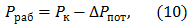
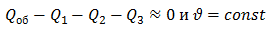
The equation of the total force of element A:
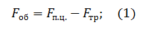
We accept that
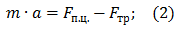
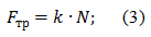
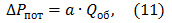
We find the frictional force by the formula:
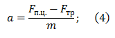
From the equation (2) we find the acceleration:
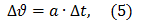
Let us find the difference between the initial and final velocities
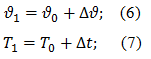
We find the speed and time:
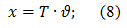
Using equations (6) and (7), we find the path:
We assume that the diameters of all three pneumatic cylinders

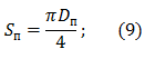
Let's find the area of the piston:
Determine the working pressure:
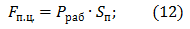
Using equations (9) and (10), we find the strength of pneumatic cylinders:
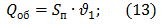
Then, using equations (9) and (6), we find the total flow rate:
We accept that
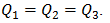
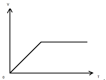
Figure 1 - Dependence of speed on time
Figure 1 shows the dependence of the velocity on time, the growth rate to
Single-acting pneumatic cylinders are used in ejectors, cutters, in clamping structures, etc. The working stroke in them is carried out under the action of compressed air, and in the initial position the rod is returned by the built-in spring or from an external load
The working stroke of the pneumatic cylinder is carried out by supplying compressed air to the piston cavity; the return stroke occurs under the action of the built-in spring, which causes less air consumption compared to double-acting pneumatic cylinders of similar dimensions. In addition, one-way pneumatic cylinders do not require full sealing of the rod cavity permanently associated with the atmosphere, and the absence of additional seals reduces friction losses. Single-acting pneumatic cylinders are used in those cases where force transfer is required only in one direction, and the return is unimpeded. and also when, for reasons of safety, the retracted position of the rod should be ensured when the power is disconnected (the pressure of the compressed air in the pneumatic system decreases). The scope of single-acting pneumatic cylinders is limited by the drawbacks inherent in this design: The operating force is reduced due to the counteraction of the spring (by about 10%); small effort in reverse (approximately 10% of the worker); limited movement of the rod (usually not more than 100 mm); increased longitudinal dimensions (the length of the compressed spring is added). There is a large number of design versions of single-acting pneumatic cylinders, for example, membrane pneumatic cylinders
The system uses also two-sided pneumatic cylinders. Double-acting pneumatic cylinders are used in those cases where it is required to transfer the operating force with linear movements in both directions, for example, when moving, installing, lifting and lowering the working parts of machines and other production and technological operations. The principal difference between double-acting pneumatic cylinders and those considered above lies in the fact that both forward and reverse piston strokes are performed under the action of compressed air with alternate supply to one of the cavities, while the other is connected to the atmosphere.
Moving the rod in either direction is operational and can be carried out under load. At the reverse stroke of the piston, the rod cavity is under excessive pressure, which is associated with the need to install additional seals on the piston and in the front cover to prevent leakage of compressed air through the rod. In piston pneumatic cylinders of one-sided and double-sided action, almost all the elements, as well as the ways of fixing them, are the same. The design of pneumatic cylinders can be different depending on their size and scope. The most common way of fixing the body parts of pneumatic cylinders with a piston diameter up to 25 mm (sometimes - up to 63 mm) is the rolling of the sleeve in the lids. This design has a significant drawback - air cylinders are not subject to repair. If the diameter of the piston is more than 32 mm, the traditional method of fastening is the tightening of the covers and the sleeve by the studs. Convenient in operation and in fact have no limitations on the diameter of the piston of the pneumatic cylinder, the covers of which are bolted to a fully-formed profiled sleeve.
The technology of production of all-round casings allows, if necessary, to carry out channels for air supply, grooves for piston position sensors; make configuration convenient for installation and maintenance.
The installation method significantly affects the performance of the pneumatic drive and the driven mechanism. Therefore, it must be chosen so that: the rod did not experience radial loads; The rod has not lost its stability in fully extended position. For stationary and for mobile mounting methods, various fasteners are available.
In cases of fixed installation, in addition to the option of directly securing pneumatic cylinders, flanges and paws are used on the equipment. To ensure the mobility of the air cylinder during operation, trunnions, swivel axles or lugs are used. Stem connections with the mechanism are also performed in various ways
Fixed connections are realized by means of an external or internal thread on the end of the rod. The misalignment of the trajectories of the end of the rod and the mounting element of the driven mechanism results in the appearance of radial forces on the rod and, accordingly, the accelerated wear of the liner, piston, rod, guide bushings and seals. If, with a rigid way of securing the rod due to operating conditions or features of the structural design of the equipment, it is impossible to prevent the occurrence of radial loads on the rod, it is necessary to use mobile transitional fasteners - fork-shaped heads, articulated tips - earrings or couplings. The earrings containing the ball element permit the rotation of the axis of the connecting hole by several degrees, and the couplings also allow radial displacement of the rod and the driven mechanism by several tenths of a millimeter. It should be borne in mind that the maximum permissible axial loads on the rod depend on the method of installation. Although the stresses in the rod from pure compression are small, at large working strokes, stability loss due to longitudinal bending is possible. Stability of the rod is verified by the generalized Euler formula. During installation, it is necessary to observe measures that preclude the possibility of damage to the cylinders (in particular the rods) and the entry of pollutants into their internal cavities. The installation locations of the pneumatic cylinders must be available for maintenance during operation.
Protection of the rod of a pneumatic cylinder from a turn
With the reciprocating motion of the rod in standard pneumatic cylinders, there is some rotation about the axis of motion, which is due to the presence of microroughness on the surface of the rod itself, as well as on the guides and seals. In this regard, directly on the rod of the pneumatic cylinder, you can not attach a tool (for example, an airbrush) that requires strict orientation in space. In order to eliminate this drawback, especially in cases where a torque is applied to the rod, various designs are used in which the stem is protected from rotation.
Positioning of pneumatic cylinders
Traditional designs of pneumatic cylinders allow to provide two points for positioning the rod and, respectively, associated with them objects - "rod retracts" and "rod extended". The area of ??effective use of pneumatic cylinders is significantly expanded if stopping and holding their output links at some given intermediate points with allowable positional errors is realized. Depending on the requirements - the number of positioning points of the output link, the frequency of their change (operating mode), the necessary accuracy of the drive by the drive of a given displacement - use pneumatic mechanisms of different structures and with different principles of controlling the movement of the output link. To provide a certain limited number of positioning points (more than two), multi-position pneumatic cylinders are used, consisting of two or more pneumatic cylinders with different working strokes.
During operation, the body of the four-position pneumatic cylinder moves, and therefore, the pneumatic cylinder must be completed when mounted with mobile connections for pneumatic hoses. The number of positioning points can be increased if more than two pneumocylinders are combined in the same way. It should be borne in mind that such structures can function unstably when the rods of different cylinders move in opposite directions.

Determine the volume of the receiver by the formula:
We calculate the actual air consumption by the formula:
Сonclusions
Calculation of the design parameters of pneumatic cylinders for the bag feeding unit from the automated packaging line. General information about pneumatic cylinders and their types are given. The principle of operation of pneumatic cylinders and their role in the working process is described. The mathematical model makes it possible to change parameters in an attempt to improve the quality of the work process.
During the design, the task was to upgrade the bag feeding unit from the cassette to the backfill.
List of sources
- Kuznetsov Yu. V., Kuznetsov M. Yu. Compressed air - 2nd ed., Pererab. and additional. - Ekaterinburg: UrB RAS, 2007. - 511 p.
- Bashta Т.М. Hydraulic drive and hydropneumoautomatics. - Moscow: Mechanical Engineering, 1972. - P. 320.
- Skhirtladze A.G., Ivanov V.I., Karev VN Hydraulic and pneumatic systems. - Moscow: IC MGTU "Stankin", "Janus-K", 2003. - P. 544.
- Mikhailov A.K., Voroshilov VP Compressor machines. - Moscow: Energoatomizdat, 1989. - 288 p.
- Bryukhanov, V.N. Automation of production. / V.N. Bruchanov. - Moscow: Higher School, 2005. - 367 c.
- http://did.camozzi.ru/#!d01g01s01p01
- http://xn--80adfdbscmorebdjpezh9nvd.xn--p1ai/shop/product/konstruktsiya-pnevmotsilindrovpnevmotsilindryi/