
Сontents
- Introduction
- 1. Theme urgency
- 2. The purpose and objectives of the study, the planned results
- 3. Review of research and development
- 4. Methods of solving the problem and current results
- Conclusion
- References
Introduction
At the enterprises of industry and housing and communal services, where a large amount of heat energy is required in the form of steam and hot water, the boiler houses are equipped with a variety of steam and hot water boilers manufactured 30 years or more ago.
The introduction of automated control systems for steam and hot water boilers, built on the basis of programmable controllers, makes it possible to automate the process of producing heat energy in boilers and greatly simplify the monitoring and management of this process. The use of such a system increases the efficiency of the boiler operation by reducing the consumption of energy resources, rational fuel combustion, the use of process equipment, the operational management of equipment and the technological process. In addition, the introduction of such systems can reduce the impact of the human factor in the production process and the likelihood of emergency operation of the boiler. Boosting the ecological characteristics of the boiler house and the culture of the production process. Thanks to the program management, the system automatically tracks all parameters of the current processes implemented by the hot water and steam boilers, and controls the process equipment, ensuring normal and trouble-free operation of the boiler plant. In addition, the system monitors the serviceability of the equipment and, in the event of breakdowns and emergency situations, signals this to the maintenance personnel.
1. Theme urgency
The indicator of the quality of the system is the specific fuel consumption, which should be minimal. However, direct operational control of this indicator is not possible, since its calculation is associated with a sufficiently long integration of fuel consumption and the load of the power unit. Therefore, numerous searches for an indirect controlled quantity were undertaken, the maintenance of which at some level would guarantee a fairly acceptable closeness of the specific consumption to a minimum.
It is known that high quality of combustion of fuel is possible only with a definite air supply to the furnace. Nitrogen, contained in the air, does not participate in combustion and, when heated, takes away a considerable amount of heat. Since the volume of air contains about 21% oxygen and 79% nitrogen and some other gases, theoretically the air volume required for burning the gas is more than the required amount of oxygen for the combustion reaction: 100: 21 = 4.76 times, and for each used cubic The oxygen meter is 79: 21 = 3.76 m3 nitrogen.
Knowing the composition of combustible gases (another fuel) and the combustion reaction, it is possible to calculate theoretically the required amount of air for the complete combustion of 1 m3 of gas (for natural gas, 17.3 mass fractions of air per one share of gas are required). However, if only the theoretically required quantity air, it is impossible to achieve complete combustion of fuel. This is explained by the fact that it is difficult to mix fuel with air so that the necessary number of oxygen molecules is fed to each molecule of combustibles. Therefore in practice it is necessary to supply air more than is theoretically necessary, i.e. work with excess air. At the same time, part of the air passes through the furnace, not reacting with fuel. The size of excess or deficit is determined by the excess air factor, which shows the ratio of the actual amount of air consumed for combustion to the theoretically necessary. The coefficient of excess air corresponds to a certain percentage of k carbon dioxide and oxygen in the flue gases.
Thus, the quality control of the combustion process can be carried out according to the content of CO2 and O2 in the flue gases. The optimum values of the air flow coefficient in relation to the fuel consumption are determined during the thermal testing of the boiler. The control of the air supply must be conducted with rather high accuracy and provide a deviation of the CO2 value by no more than ± 0.5% (with fluctuations in the CO2 content of the flue gases, on the average, 8–12%)
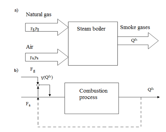
Figure 1 – Scheme of analysis of the process of combustion of fuel
In Fig. 1a is a diagram of the analysis of the process of burning fuel in a steam boiler as a control object in terms of material flows and their information variables.
The main technological goal of the combustion quality process is to ensure the O2 content in the off-gas, so stabilization of the O2 concentration in the flue gases must be ensured by changing the air flow rate Fa. Therefore, as a regulated value, it is necessary to take the concentration in the off-gases, and the regulating effect is realized by changing the air flow rate Fa.
To improve the quality of regulation, as well as to ensure the optimum value of the airflow coefficient in relation to fuel consumption, it is necessary to provide a system for regulating the air flow rate ratio Fa, depending on the gas flow (fuel) Fg.
As control parameters, it is necessary to select the air concentration in the exhaust gases, the air flow rate Fa, the gas flow Fg, the gas pressure Pg, the air pressure Pa.
On the basis of the analysis we compose a functional diagram of the process of automatic control of the process of fuel combustion quality (Fig. 1b).
2. The purpose and objectives of the study, the planned results
The purpose of the work can be formulated as follows: ensuring a minimum specific fuel consumption, improving the quality of the combustion process, due to the optimal ratio of fuel-air costs with correction for the temperature of the air sent to the boiler furnace.
To achieve this goal, it is necessary to solve the following tasks:
- Analyze the technological diagrams of the combustion process.
- Analyze the technological process of fuel combustion as an op-amp from the point of view of the main material flows and information variables.
- Develop a functional scheme and perform a selection of hardware for the implementation of the ACS.
- Perform synthesis of ACS.
- DTest the performance of the automatic control system by mathematical modeling.
Object of the study: DKVR–6,5 / 13 GM boiler.
3. Review of research and development
It is known that high quality of combustion of fuel is possible only with a definite air supply to the furnace. In the existing automation systems, the fuel-air scheme is presented, which solves this problem (Fig. 2). The regulator of air supply to the combustor chamber acts on the regulating air supply. Its input is supplied by the difference between the actual airflow Gb and its set value G3b, which is generated in the command unit (KU), depending on the fuel consumption Gt change in the pre-compiled mode map. The mode map can be corrected by the application of the influence (the excess air factor) [6].
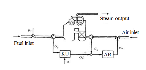
Figure 2 – Functional diagram of automating the fuel-air ratio
Note that, since fuel consumption is changed by the steam pressure regulator, the above scheme should be considered as part of an autonomous two-dimensional system that controls both the vapor pressure and the combustion quality of the fuel. Next, we will consider a method for maintaining the optimum fuel-air ratio of a boiler plant which controls the supply of air based on the analysis of the composition of the flue gases, in this case at a signal proportional to the oxygen or carbon monoxide content generated by the gas analyzers. A possible block diagram of the fan drive control system is shown in Fig. 3.
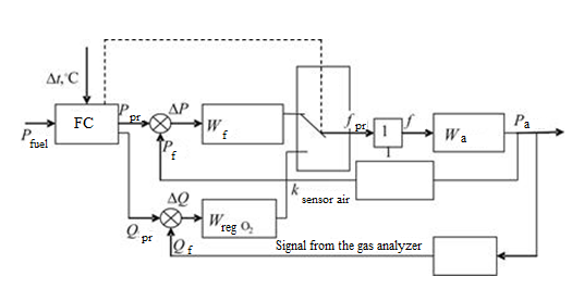
Figure 3 – Block diagram of the fan motor control system
The system contains two circuits: primary and secondary. The main loop for controlling the supply of air to the furnace is a circuit based on air analysis by the amount of residual oxygen in the flue gases. An obligatory feedback signal for the operation of the main circuit is the analog signal from the gas analyzer sensor. The oxygen reference signal (set in the microprocessor programmable controller) and the feedback signal are compared, the error signal is fed into the control system by an analogue or digital controller.
When the boiler is ignited and at the initial section of its capacity, the composition of the exhaust gases differs little from the composition of the air entering the combustion chamber. Therefore, the control system, closed by the signal of the gas analyzer, is inefficient, and there is a need for an additional circuit. The additional circuit operates according to a given fuel-air ratio. The signal of the gas pressure sensor is the master signal for the control of the electric drive of the fan by the additional circuit.
4. Methods of solving the problem and current results
The main loop for controlling the supply of air to the furnace is a circuit based on air analysis by the amount of residual oxygen in the flue gases. An obligatory feedback signal for the operation of the main circuit is the analog signal from the gas analyzer sensor.
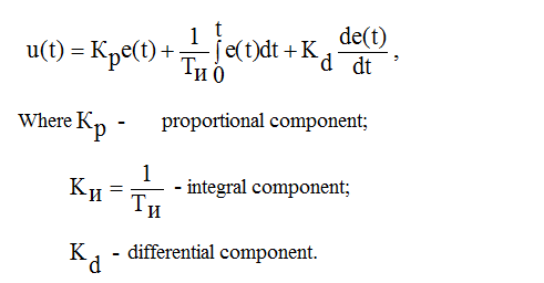
The outlet of the air concentration at the setpoint of 5.7% requires the adjustment of the external regulator by concentration. Since the control channel concentration – air flow
has a large inertia, and also based on practice, it is necessary to select the PID control law:
The analysis of the dynamics of the main elements of the cascade ATS was carried out on the basis of the modeling scheme shown in Fig. 4
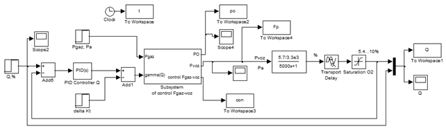
Figure 4 - Diagram of simulation of the dual-circuit ATS oxygen concentration in the flue gases
From the ATS scheme (Figure 4), it is clear that the output of the concentration regulator is the driving force for the internal contour of the gas–air ratio. Then follows the model of the inner contour of the relationship, considered above.
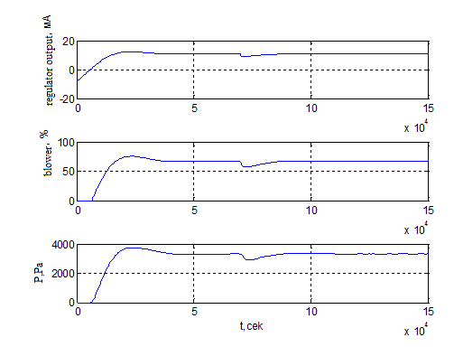
Figure 5 - Graphs of the transient processes of the ratio controller, blower and air pressure when working out the setpoint concentration by 5.7%
The results of the automatic tuning provided the specified requirements for the quality of the transient process (Figure 5): aperiodic nature of the transient with a 9% overshoot; Settling time (regulation) tp = 5000sec = 1.3 hours.
The transient characteristics of the flow rate regulator and the blower output, taking into account the imposed constraints, are shown in Fig.5.
In modeling ATS, we analyze the response of the transition characteristic in terms of the oxygen concentration to a decrease in the temperature of the air supplied to the furnace. A change, namely, a decrease in temperature, leads to a change in the ratio of the ratio γ(Qo2)*(1-Δkt), and, accordingly, the decrease in the air flow rate. From Fig. 5 that the transient control process has a smooth aperiodic character without bursts, does not go beyond the limitations, which is good from the point of view of the technical conditions of operation of the boiler plant.
Conclusion
1. Analysis of existing ACS allowed to formulate the task of management. It is necessary to synthesize and investigate the ACS TP of burning fuel. The process control scheme for the quality of fuel combustion should take into account practically all fluctuations in fuel quality, the temperature of the air supplied to the combustion chamber. This can be achieved by cascading control and the possibility of the automation system, both with normal boiler output and in the ignition mode.
2. The main tasks are determined, the solution of which will allow to develop an effective control system with energy-intensive management.
3. A mathematical model of the combustion process is obtained, which is an inertial object with a transient delay, as well as a mathematical model of the actuator that takes into account technological real limitations on input and output signals.
4. The results of modeling prove the operability of ATS and the possibility of using the developed systems in boiler plants.
The main indicators of regulatory quality are as follows:
-the absence of a static error;
-the regulation time is about 1.3 hours;
-periodic character of transient processes with permissible overshoot equal to 9%;
-a satisfactory time for working out a perturbation with respect to air temperature 0.5 hours.
References
- Липов Ю. М. Котельные установки и парогенераторы.–Ижевск: Регулярная и хаотическая динамика, 2003. – 592 с.
- Денисенко В. В. ПИД–регуляторы вопросы реализации часть 2// СТА.2008. № 1. с 86–99
- Мухин О.А. Автоматизация систем теплогазоснабжения и вентиляции: Учеб. Пособие для вузов.– Мн.: Выш.шк.,1986–304с.:ил.
- Управление вентилятором [Электронный ресурс] / – Режим доступа: http://studopedia.su/17_44596_upravlenie-ventilyatorom.html.
- Мухин В.С., Саков И.А. Приборы контроля и средства автоматики тепловых процессов: Учеб. Пособие для СПТУ.– М.: Высш. шк., 1988.– 256с.: ил.
- Регулирование нагрузки котла [Электронный ресурс] / – Режим доступа: http://studopedia.su/17_44593_regulirovanie-nagruzki-kotla.html.
- Паровые котлы серии ДКВР [Электронный ресурс] / – Режим доступа: http://mmzavod.com.ua/index.php/produktsiya/parovye-kotly/7-parovye-kotly-serii-dkvr.
- Система автоматического управления котельной с одногорелочными котлами малой мощности [Электронный ресурс] / – Режим доступа: http://www.syst.ru/vnedren/kot_mm.htm.
- Бейрах 3. Я., Вывод уравнений динамики барабанного парового котла, Автомат. и телемех., 1939, выпуск 2, с89–104 [Электронный ресурс] / – Режим доступа: http://www.mathnet.ru/links/2250ff82389342115dd2781d7d2ea28f/at13912.pdf.
- Волошенко В. А.Принципиальные схемы паровых котлов и топливоподач: учебное пособие/ А.В. Волошенко, В.В. Медведев, И.П. Озерова; Томский политехнический университет. – Томск: Изд–во Томского политехнического университета, 2011.–100с.
- Бородин И.Ф. Автоматизация технологических процессов: учеб. пособие / И.Ф. Бородин, Ю.А. Судник. – М., 2004. – 344 с.
- Овчаренко Н.И. Автоматика электрических станций и электроэнергетических систем: учеб. пособие / Н.И. Овчаренко; под ред. А.Ф. Дьякова. – М., 2000. – 504 с.
- Системы автоматизации котлов [Электронный ресурс] / – Режим доступа: http://engineeringsystems.ru/teplogeneriruyuschiye-ustanovki-sistem-teplosnabzheniya/sistemi-avtomatizacii.php.
- Гичёв Ю.А. Источники теплоснабжения промышленных предприятий. Часть І: Конспект лекций: Днепропетровск: НМетАУ, 2011. – 52 с.
- Автоматика регулирования работы котлов тлов [Электронный ресурс] / – Режим доступа: http://www.bibliotekar.ru/spravochnik-101-kotly/15.htm.