
Bychkov Victor Igorevich
Faculty computer information technologies and automatics
Automation and telecommunications department
Speciality Сontrol in Technical Systems
Research and development of a universal GSM‐controller for alarm, monitoring and control systems of remote objects
Scientific director: Ph.D., professor Sukov Sergey Feliksovich
Abstract
Warning! This abstract refers to a work that has not been completed yet. Estimated completion date: June 2018 Contant author after that date to obtain complete text.Content
- 1. Theme urgency
- 2. Goal, tasks and current results
- 3. Designing a universal GSM‐controller
- 3.1 Structural diagram and basic elements of the controller
- 3.2 Description of the work principle
- 3.2.1
Configuration
- 3.2.2
Alert
- 3.2.3
Monitor
- 3.2.4
Control
- Conclusion
- References
Introduction
Due to the fact that mobile phones and smartphones are widely used today and the cellular environment is used as the transmission medium, the GSM standard is widely used for remote access to automated process control systems (APCS), namely to programmable logic controllers (PLC). Such access allows remote monitoring of data at the entrances, control of the statuses at the controller outputs, adjustment of configurable parameters of the PLC program, change of the control system settings and saving of the specialist on the site of the implementation of automated control systems for technological interaction. The standard of GSM cellular communication ensures the transfer not only of voices, but also of data, and reliability and reliability in the exchange of information, high speeds, as well as the ability to organize remote control and receive a response to a subordinate situation that meets the requirements in various industries, developers of process control systems. In view of this, the technologies and basic solutions based on cellular communication aroused the interest of specialists and managers of enterprises and commercial structures [1].
1. Theme urgency
To date, GSM‐controllers have a wide prevalence and relevance in automated control systems, smart home systems, fire and security alarm systems, access control systems, etc., which are built on the basis of several controllers that use the functions of either alerting, either monitoring or controlling. Actual and popular are universal GSM‐controllers. Universality means that on the basis of one GSM‐controller it is possible to build a system with functions and notifications, and monitoring and control of remote objects, as well as the ability to set (via PC) and remotely change (via GSM communication channel) controller settings. In fact, the universal GSM‐controller combines all the basic functions of GSM‐controllers, which consist of the above-mentioned systems.
2. Goal, tasks and current results
The purpose of the research is to improve the universal GSM‐controller for alarm, monitor and control automation systems using remote access through the GSM cellular channel.
Tasks of the research:
- review and analysis of existing GSM‐systems of remote control;
- determination of the required AT commands and testing them for compatibility with the modem;
- development of technical specifications;
- development of the controller's structural and schematic diagram;
- software development;
- field test controller.
As part of the master's work, it is planned to manufacture devices - a universal GSM‐controller, in which the operation modes Alert
, Monitor
, Control
and Configuration
, their functions and subfunctions, as well as the possibility of using one, two or all three modes simultaneously. It should be possible to use the Configuration
mode both via GSM and via USB, using specially developed software on the PC. Table 2.1 shows the functions and subfunctions of the controller's operating modes.
Table 2.1 — Functions and subfunctions of operating modes of the universal GSM‐controller
| Operating mode | Functions | Subfunctions |
| Alert | 1. Checking the status of the controller inputs | 1. Checking for an active level of a digital input | 2.Checking achieve or go beyond the established analog input signal range limits | 2. User notification about changing input states | 1. Notification by SMS | 2. Call notification |
| Monitor | 1. Getting the current state of analog and digital inputs | 1. Getting the current state of the digital input | 2. Receiving the current state of the analog input | 2. Informing the user about the current state of the analog and digital inputs | – |
| Control | Changes in the state of the outputs by the user's command | 1. Change the status of digital outputs by sending an SMS message | 2. Changing the status of digital outputs using DTMF commands | 3. Change the state of analog outputs by sending an SMS message |
| Configuration | 1. Add or change a user number | – | 2. Change the password for accessing settings | – | 3. Change the notification number | – | 4. Setting Alertmode |
1. Power On/Off mode | 2. Activation/Deactivation of digital inputs | 3. Activating/Deactivating of analog inputs | 4. Select an alert type | 5. Setting Monitormode |
1. Power On/Off mode | 2. Activation/Deactivation of digital inputs | 3. Activating/Deactivating of analog inputs | 6. Setting Controlmode |
1. Power On/Off mode | 2. Activation/Deactivation of digital inputs | 3. Activating/Deactivating of analog inputs | 4. Choice of type of duty cycle | 5. Specifying the period for changing the duty cycle |
3. Designing a universal GSM‐controller
3.1 Structural diagram and basic elements of the controller
The block diagram of the universal GSM‐controller is shown in Fig. 3.1. As can be seen from the figure, the GSM controller being developed consists of a power supply, a microcontroller, a GSM modem, a DTMF decoder and analog/digital inputs and outputs.
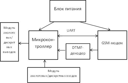
Figure 3.1 — Block diagram of the universal GSM‐controller
This device uses the microcontroller of ATMEL ATmega8L company, the GSM‐modem of SIMCom SIM900 is used as channel-forming equipment, and the DTMF decoder BT8870 is made by Altech corporation. The universal GSM‐controller has two discrete and two analog inputs, as well as two discrete and two analog outputs.
3.2 Description of the work principle
3.2.1 Configuration
mode
Before the first start of the device, initialization of the controller parameters, performed by the functions and subfunctions of the Configuration
mode, is necessary. Initialization of parameters is carried out with the help of special software designed for the Configuration
mode. Figure 3.2 shows a software window in which the user numbers of the Configuration
mode are presented.
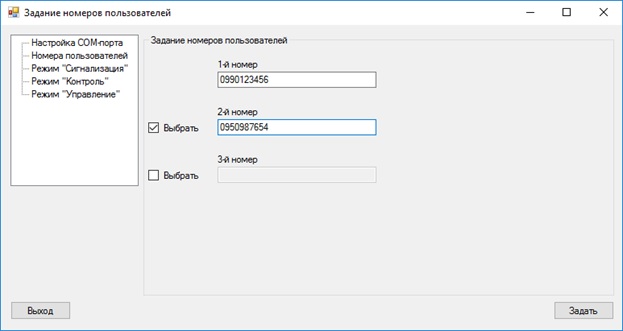
Figure 3.2 — The software window for setting user numbers of the Configuration
mode
The parameters are transferred from the PC to the controller via the UART interface in the form of special commands, the form of which is the following:
\[operation mode][space][command’s name][space][parameters].
The symbol \
indicates the reception of the command, and the symbol .
- at the end of the command reception. After the \
symbol, the name of the mode is specified, which defines the function of the Configuration
mode. The command name defines a function subfunction or only a function (if there are no subfunctions) of the mode. The parameter specifies the values 0 or 1
(with the exception of the functions Adding and changing the user number
, Changing the access password to settings
and the sub-function Specifying the period of change in the duty cycle
). Figure 3.3 shows an example of the command to turn on/off the Control
mode, and in Figure 3.4 - an example of changing the notification number
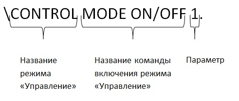
Figure 3.3 – Command to turn on/off the Control
mode
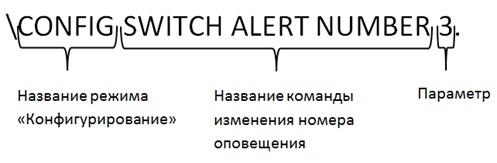
Figure 3.4 – Change notification number command
You can also change the settings using the GSM channel. The command pattern for the Alert
, Monitor
and Control
modes is similar to the previous commands, but for the Configuration
mode has a different appearance:
\[access password][space][operation mode][space][command’s name][space][parameters].
The access password is necessary to ensure the security of access to the controller settings. The remaining fields are similar to the fields of the commands of other operating modes.
3.2.2 Alert
mode
The principle of this mode is:
- the constant execution of the function
Checking the state of the controller inputs
in each clock cycle of the microcontroller, if it is not occupied by another operation; - to perform the function
User notification about the change of the input states
.
The subfunction Checking for an active level of a digital input
checks the presence of a logic zero (active level) on the contact of the microcontroller to which the digital input is connected. The subfunction Checking achieve or go beyond the established analog input signal range limits
compares the value of the ADCH register with the values of the user-defined range limits. If an active level has appeared on one discrete input, or there has been an achievement/transition beyond the established boundaries on one analog input, an SMS message is generated, the text of which contains the number and name of the input and its state, or the first (default) number the user. The system continues to notify the user every three minutes until he makes a call to the modem, and the controller does not reset this call (after checking the phone number), after which an SMS message with the text User notified
is generated and sent to the user for confirmation, that alerts have been discontinued. Figure 3.5 demonstrates the operation of the Alert
mode.
Figure 3.5 – Operation of the Alert
mode
(animation: 13 frames, 5 repetition cycles, 65 kilobytes)
(Di – discrete inputs, Ai – analog inputs)
The method of notification can be selected using the subfunction Select an alert type in the function
Setting
in the Alert
modeConfiguration
mode. By default SMS notification is selected.
3.2.3 Monitor
mode
The principle of the Monitor
mode consists in performing two functions in turn: Getting the current state of analog and digital inputs
. The first function starts its execution on the user's request, i.e. after the controller receives an SMS message from the user number, or after answering the call and receiving the DTMF command. The text of the SMS message is the text of the command of the following type:
?CONDITION[space][input’s type][space][input’s number]
The symbol ?
indicates command reception of the Monitor
mode.
The DTMF command is formed from DTMF tones that correspond to the keys on the phone's keypad. With the DTMF decoder of the BT8870, the two-tone multi-frequency signal is decoded into a binary code that is checked by the microcontroller. The DTMF command is as follows:
*[operation mode][function][subfunction]#
The symbol *
indicates the reception of the command, and the symbol #
- at the end of the command reception. In the field operating mode
the figures from 1 to 4, corresponding to the operating modes of the controller are indicated:
- 1 –
Configuration
mode ; - 2 –
Alert
mode ; - 3 –
Monitor
mode ; - 4 –
Control
mode .
In the function
field, the function number of this mode is indicated, and in the subfunction
field - the subfunction number of this function. The function and subfunction numbers are listed in Table 2.1. This type of DTMF commands is used in all other modes except for the Configuration
mode, because DTMF commands are not applied for this mode. Figure 3.6 shows an example of a DTMF command for obtaining the current state of a binary input.
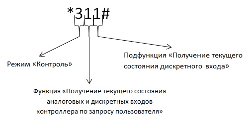
Figure 3.6 — DTMF command for getting the current state of the digital input
After receiving this DTMF command, or SMS message with the text ? CONDITION DIS 1
, the second function of the Monitor
mode starts - Informing the user about the current status of analog and digital inputs
. The essence of this function is to generate and send an SMS message to the user with the following text:
[input’s number][space][input’s type][dash][input’s state]
For the previous command, the message text is as follows: 1 DIS INPUT-OFF
.
For analog inputs, the input state
field indicates the current input value obtained from the ADCH register.
If the function does not have subfunctions, then in the subfunction
field the digit 0 is entered.
3.2.4 Control
mode
The principle of this mode is to perform the function Changes in the state of the outputs by the user's command
and its subfunctions. This function starts, as in the Control
mode, with the user's request in the form of an SMS message or a DTMF command. The use of DTMF commands in the Control
mode is possible only for the subfunction Changing the status of digital outputs using DTMF commands
. The text type of the SMS message is as follows:
!CHANGE[space][input’s number][space][input type][dash][state]
The symbol !
indicates the command reception of the Control
mode. The status
field indicates ON
or OFF
for the digital outputs. These words indicate switching on or off the output.
Analog outputs are PWM (pulse width modulation), which are divided into two subtypes: with a constant and with a variable duty cycle. The subtype is selected in the sub-function Choice of type of duty cycle
in the function Setting the
Control
mode of the Configuration
mode.
If a subtype with a fixed duty cycle is selected, then the user can change the value of the duty cycle by means of SMS messages, indicating a new value in the state
field of the message text. If a subtype with a variable duty cycle is selected, the user specifies in this field the value of the change period (duty cycle) of the duty cycle in percent.
Conclusion
The analysis of the sources showed that the topic of research and development of the universal GSM‐controller is relevant not only in the international but also in the national and local scientific communities.
The requirements for a universal GSM‐controller have been put forward and the operating principles of the controller modes and its functions and subfunctions have been described, and a structural diagram of the universal GSM controller has been provided, texts of SMS messages and DTMF commands have been demonstrated.
Further work will be aimed at improving and finalizing the software on a PC and microcontroller, developing a circuit diagram of the device, adding the possibility of using DTMF commands in the Control
mode for analog outputs.
References
- Применение GSM/GPRS‐технологий для построения эффективных АСУ ТП // http://genisys.ge. [Электронный ресурс]. – Режим доступа: http://genisys.ge/ru/news/применение-gsmgprs-технологий-для-построения-эффективных-асу-тп
- Rongrong Zhang A Smart Home System Design Based on GSM / Zhang Rongrong, Zou Xiaoping, Huang Wenhui, Surong Qimu // Communications and Network. – 2013. – Vol.5, No.1B. – С. 25 – 28.
- Елисеев А. Универсальный модульный контролер с ядром ARM9 / А. Елисеев // Современная электроника. – 2011. - №2. – С. 54 – 63.
- Минаев А., Ващенко Ю. RIT35 – современные GSM системы мониторинга / А. Минаев, Ю. Ващенко // Современная электроника. – 2006. - №9. – С. 42 – 43.
- Вальпа О. Микроконтроллерная система безопасности с использованием GSM‐канала / О. Вальпа // Современная электроника. – 2007. - №9. – С. 34 – 37.
- Грудинин А. А. Система сигнализации автомобиля на базе GSM/GPS/FPGA технологий: статья из сборника / А. А. Грудинин, , А. А. Похомов, К. В. Медведев, А.И. Медгаус, Е. Ю. Зинченко. – Д.: ДонНТУ, 2010. – 17 с.
- Применение GSM‐канала в системах охраны (Часть 1) // daily.sec.ru [Электронный ресурс]. – Режим доступа: http://daily.sec.ru/2010/03/22/AI-Avramchuk-Primenenie-GSM‐kanala-v-sistemah-ohrani-CHast-1.html.
- Применение GSM‐канала в системах охраны (Часть 3) // daily.sec.ru [Электронный ресурс]. – Режим доступа:http://daily.sec.ru/publication.cfm?pid=24828.
- AVR. Учебный курс. Передача данных через UART // Easy Electronics [Электронный ресурс]. – Режим доступа: http://easyelectronics.ru/avr-uchebnyj-kurs-peredacha-dannyx-cherez-uart.html.
- UART. Применение в электронных проектах // GetChip [Электронный ресурс]. – Режим доступа: http://www.getchip.net/posts/044-uart-primenenie-v-ehlektronnykh-proektakh/.
- Управление GSM модулем с AVR // Geek Times [Электронный ресурс]. – Режим доступа: https://geektimes.ru/post/255530/.
- Мясищев А. А. Удаленное управление устройствами с помощью микроконтроллера Atmega8 и мобильного телефона, поддерживающего AT команды. Технология GSM умный дом // Практика для студентов [Электронный ресурс].– Режим доступа: http://webstm32.sytes.net/user-files/lab/lab2_avr_gsm.htm.
- AVR. Учебный курс. Использование ШИМ [Электронный ресурс]. – Режим доступа: http://easyelectronics.ru/avr-uchebnyj-kurs-ispolzovanie-shim.html.
- AT-команды GSM модема SIM900 // alex_exe.ru [Электронный ресурс]. – Режим доступа: http://alex-exe.ru/radio/wireless/GSM‐sim900-at-command/.