
Content
- Introduction
- 1. Purpose and objectives of the study
- 2. Overview of methods and tools for measuring gas flow
- 3. Characteristics of the ultrasonic measurement method
- 3.1 Advantages and disadvantages of ultrasonic gas flowmeters
- 3.2 Principle of operation of ultrasonic gas flowmeter
- 4. Technical requirements for development
- 5. Choice of converter time-code chip
- 6. Development of the flow chart of the flowmeter
- 7. Method for measuring the time of flight of a pulse
- 8. The development of automatic gain control (AGC)
- 9. Development of a filter for suppressing acoustic noise
- Conclusions
- List of sources
Introduction
Creation of new technologies and production processes and increase in cost energy resources led to the fact that the need to measure gas consumption has increased. Nowadays There are a huge number of flowmeters that use different methods of measuring flow, differing only in the field of application and metrological characteristics. Methods using acoustic waves are the most promising. This is due to the fact that acoustic oscillations and waves are universal carriers of information about this or that state of objects. Ability spread in different environments and the simplicity of radiation – the reception of ultrasonic waves, makes it possible use ultrasonic flowmeters to measure gas flow in pipelines.
Over the past 15 years, ultrasonic gas meters have passed from the engineering laboratory before serial use as the main instrument for measuring the volume of gas for commercial accounting. Along with high reproducibility and high accuracy, ultrasonic technology has other characteristic features: insignificant pressure drop; wide measurement limits; Ability work with reversible flows; resistance to pollution and extensive self-diagnosis capabilities.
1. Purpose and objectives of the study
The aim of the paper is to substantiate the structure of an ultrasonic flowmeter capable of operating in a wide range of measured velocities and gas pressures under conditions of acoustic interference.
Main research tasks:
- To choose a time-code converter that provides the required accuracy and resolution of the measurement of the time of flight of ultrasonic pulses.
- Develop a flow chart of the flowmeter and an algorithm for its operation.
- Develop a system of automatic gain control (AGC).
- Develop an electrical filter to suppress acoustic interference.
2. Overview of methods and tools for measuring gas flow
One of the most important tasks in the gas industry is the measurement of gas consumption. The system of accounting for the quantity of substances is impossible without means flow measurements that are based on different flow measurement methods.
The flowmeter performs the following functions:
- Output of the results of measurements of volume, flow, temperature, pressure on the indicating device;
- Input of values of conditionally constant values: gas composition, parameters of pressure and temperature sensors, correction factors, calibration factors;
- Protection against unauthorized access to parameters;
- Remote transmission of measured data;
- Ensuring intrinsic safety requirements.
Currently, the following types of flowmeters are used:
- Ultrasonic flowmeter of gas. Principle of operation of ultrasonic electronic flow meter-counter gas is based on the fact that the transducers send and receive pulses passing through the medium. The ultrasonic flowmeter-gas meter measures the difference in the time of flow of signals along the flow and against it, using various methods of digital signal processing, determines the speed and volumetric flow.
- Inkjet flowmeter. The principle of operation of industrial digital gas (air) flowmeters is based on the dependence of the oscillation frequency of the jet of the medium to be measured in the sensor element of the flowmeter from volume flow of gas flowing through it.
- Coriolis flowmeter.The principle of operation is based on changes in the phases of mechanical oscillations U-shaped tubes, through which the medium moves.
- Thermoanemometric flowmeters. The current gas flow rate is calculated from the value the dissipated thermal power of the thermoanemometer, the composition and thermophysical properties of the gas, the parameters pressure, as well as the dimensions of the sensing element of the primary transducer and the area of the transverse section of the pipeline.
The ultrasonic industrial gas meter uses the most promising technology to date ultrasonic flow measurement.
3.Characteristics of the ultrasonic measurement method
3.1 Advantages and disadvantages of ultrasonic gas flowmeters
Along with high reproducibility and high accuracy, ultrasonic technology has other characteristic features:
- low pressure drop;
- wide measurement limits;
- ability to work with reversible flows;
- resistance to pollution and extensive self-diagnosis capabilities.
To the drawbacks of ultrasonic flowmeters, which restrain their wide distribution, it is necessary to relate:
- the complexity of implementing stringent requirements for the accuracy of measuring time intervals; accuracy of measurements should be no worse than 0,4 ns to provide a speed resolution of 0.001 m / s according to GOST (GOST ISO17089 Measurement of flow in closed channels – ultrasonic gas meters);
- the effect of acoustic interference;
- dependence of the level of the measuring signal on the gas pressure.
3.2 Principle of operation of ultrasonic gas flowmeter
The principle of operation of the flowmeter is based on the method of measuring the difference between the time of passage of ultrasonic momentum along the flow and against the gas flow. The measured time difference proportional to the flow rate is converted in the value of the gas volume flow.
The time of sound propagation in the direction of flow
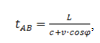
where L – is the distance between the sensors (the path length of the beam), m;
с – is the speed of sound, m/s;
v – flow velocity, m/s;
φ – the angle between the acoustic beam and the direction of the flow (see Fig. 1).
Figure 1 – Principle of operation of an ultrasonic gas flowmeter
(Animation: 19 frames, the number of repetitions: unlimited;
321 kilobytes)
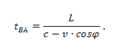
Time of sound propagation against a stream
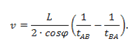
Flow rate
Volumetric flow of gas in operating conditions

where S – is the cross-sectional area of the flowmeter, m2.
Gas volume in standard conditions
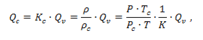
where Kc – is the coefficient of reduction to standard conditions;
ρ – gas density, kg/m3;
ρс – gas density under standard conditions;
P – absolute gas pressure, MPa;
Рс – standard gas pressure, 0.1013 MPa;
Т – gas temperature, 0С;
Тс – standard gas temperature, 20 ° C;
К – coefficient of gas compressibility (depends on the gas composition).
The theoretical speed of sound can be obtained from the gas composition, its temperature, and pressure. This theoretical speed of sound should be identical to the measured speed. In this way, speed of sound provides a good opportunity to diagnose the system.
4. Technical requirements for development
Requirements for ultrasonic gas flowmeter:
- range of measured flow velocities from 0.2 to 40 m/s
- speed resolution of 0.001 m/s
- conditional diameter from 50 to 500 mm
- limit of permissible relative error ± 1%
- gas overpressure range from 0 to 10 MPa
- gas temperature range from -50 to +70 ?С
5. Choice of converter time-code chip
TDC-GP22 – universal two-channel time-digital converter with serial interface, adapted for ultrasonic flowmeters.
An important feature is the property of detecting the first wave of a sequence of pulses, which increases the speed of the flowmeter.
Technical advantages:
- 1 channel with a resolution of 90 ps
- Double resolution mode 45 ps, Four-shot mode 22 ps
- Measuring range from 500 ns to 4 ms
- Possibility of fixing and automatic processing of all 3 events
As a result of the analysis of possible circuit solutions, the time interval meter was chosen a specialized GP-22 chip providing a resolution for measuring time intervals about 90 ps (at the required 400 ps);
Figure 2 – GP22 chip
6. Development of the flow chart of the flowmeter
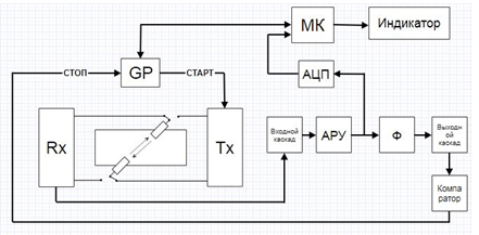
Figure 3 – Structural diagram of an ultrasonic gas flowmeter
7. Method for measuring the time of flight of a pulse
The principle of operation of ultrasonic flowmeters can be based on measurement time intervals directed alternately along and against the flow.
After applying to the ultrasonic transducer transmitting a short voltage pulse with a duration of the order of 4 ?s (half the period of resonance oscillations of the sensor), a spatial sound wave in the direction of the receiving sensor. The measuring signal received by the sensor is A complex form formed by adding two harmonic oscillations with close frequencies and different amplitudes. Typical type of the oscillogram of the measuring signal obtained at the output of the preliminary amplifier is shown in Figure 4.
To measure the transit time of ultrasonic vibrations, the signal is further amplified and the first information impulse with the amplitude of the higher level of comparison (the half supply voltage) (see Figure 5).
During the time span of the pulse, the time interval between the shot and the moment of operation of the comparator is taken.
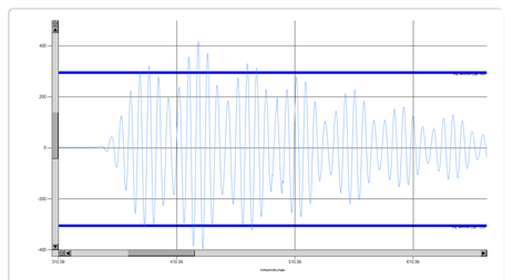
Figure 4 – Oscillogram at the output of the preamplifier
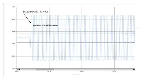
Figure 5 – Oscillogram at the output of the terminal amplifier
8. The development of automatic gain control (AGC)
The AGC system is necessary to stabilize the required signal level at the output of the measuring amplifier in a wide range of gas pressures from 1 to 100 atmospheres in flowmeters with a diameter of 50 to 500 mm. It is known that The signal level is proportional to the gas pressure and inversely proportional to the distance between the ultrasonic sensors. Thus, the AGC system should be able to control the gain of the measuring amplifier not less than 1000 times. It is proposed to perform AGC on the basis of the tracking system with a stepped change in the gain in steps of 5%.
It is proposed to perform AGC on the principle of a servo system with a step change in the gain in steps of 5%. If the level of the measuring signal is less than the nominal value, then the AGC system will be sequentially Increase the gain in steps of 5%, if more – to reduce.
Determine the required number of stages of gain control
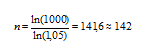
Figure 6 shows the proposed circuit solution of the AGC amplifier. The amplitude of the measurement signal is stabilized by controlling the transmission factor amplifier stage on the op-amp (DA) DA1 using two 7-bit digital potentiometers R1 and R2.
Adjustment of the transmission factor is carried out on the basis of the tracking system. If the measured amplitude the measuring signal is less than the required one, then the transmission factor is increased by one step (by 5%), if the amplitude is greater, the transmission factor decreases by one step.
The range of possible values of the transmission factor of the AGC amplifier: from 0.05 to 50. The number of stages of the transmission coefficient: 142.
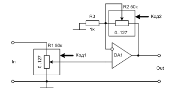
Figure 6 – AGC amplifier
Here are the main design relationships for the amplifier circuit of the AGC system.
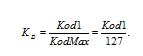
The input divider transmission ratio on the potentiometer R1
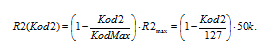
Potentiometer resistance R2
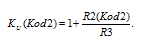
Amplifier gain on the op amp without an input divider
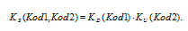
The total transmission gain of the AGC amplifier
We perform mathematical modeling and determine the relative measurement of the gain of the AGC amplifier when the codes of potentiometers Kod1 and Kod2 are changed to one. The simulation results are shown in Figures 7 and 8, respectively. From the results it follows that these dependences are nonlinear and this makes it very difficult to determine the required the values of the codes of the digital potentiometers for the realization of the stepwise gain control with the selected step of 5%.
To solve the problem of determining the required values of the codes of the digital potentiometers R1 and R2 for each of the 142 levels of gain control AGC developed a program in the Delphi environment. This program of 16,384 possible combinations of digital potentiometer codes selects 142 codes providing the required adjustment step. The window of the program with the results of calculations is shown in Fig.9.
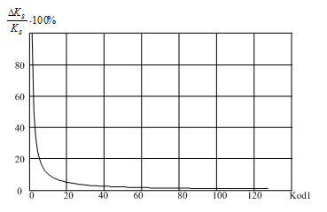
Figure 7 – Dependence of the relative change in the gain of the AGC amplifier when the digital potentiometer R1 is changed per unit code
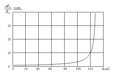
Figure 8 – Dependence of the relative change in the gain of the AGC amplifier when the digital potentiometer R2
The program implements the following algorithm. First, an array of all possible values of the transmission coefficient amplifier AGC KS from 0.008 to 51 with alignment in ascending order. A total of 16,384 values. Then it calculates the necessary 142 values of the gain of the AGC amplifier with the selected step of 5% from 0.05 to 51. In the third final step, the program forms the final array of AGC coefficients.
The level of the measuring signal is determined and stabilized by the amplitude of the first bend (see Fig. 10).
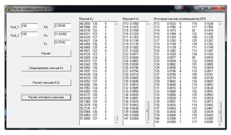
Figure 9 – Delphi program for calculation of AGC coefficients
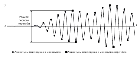
Figure 10 – Determination of the level of the measuring signal from the amplitude of the first inflection
9. Development of a filter for suppressing acoustic noise
In various fields of activity of modern society, when using acoustic systems in a confined space, The problem of suppressing acoustic noise remains urgent. Such hindrances arise in the most diverse spheres of human activity - when scoring rooms, in tactical and flight headsets, in hearing aids, in research systems with emitters and receivers of audio signals, etc.
To suppress the acoustic noise signal, it is proposed to introduce a cascade of active high-pass filter with a cutoff frequency of about 120 kHz. The filter will not practically weaken the useful a measuring signal with a frequency of 125 kHz, and will effectively suppress the interference signal with a frequency of about 30 kHz.
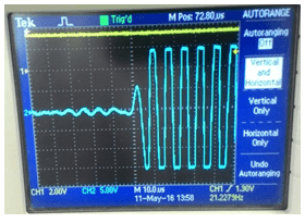
Figure 11 – Oscillogram without acoustic interference
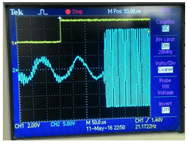
Figure 12 – Oscillogram with acoustic interference
Conclusions:
- The requirements to the structural elements of the industrial ultrasonic gas flowmeter are justified, capable of operating over a wide range of measured velocities and gas pressures under conditions effects of acoustic interference.
- The proposed AGC system of ultrasonic gas flowmeter realizes the principle of tracking systems with a step-by-step adjustment of the transmission gain of the measuring amplifier in steps of 5% and provides a range of transmission ratio adjustment of at least 1000.
- The program for calculating the array of coefficients of digital potentiometers developed in the Delphi environment allows from 16384 possible combinations of codes (positions) of digital potentiometers R1 and R2 to select 142 values ??that provide the required step of adjusting the gain of the AGC amplifier equal to 5%.
- The structural diagram of the ultrasonic gas flowmeter is constructed.
Список источников
- Реент А.В.,Кузнецов Д.Н. Обоснование структуры промышленного ультразвукового расходомера газа/А.В. Реент, Д.Н. Кузнецов – Физика и техника – 2016 / Материалы научно-практической конференции. - 2016. – С.34-35.
- Реент А.В.,Кузнецов Д.Н. Система автоматической регулировки усиления для ультразвукового расходомера газа/А.В. Реент, Д.Н. Кузнецов - Автоматизация технологических объектов и процессов поиск молодых. /Сборник научных трудов конференции. — Донецьк, ДонНТУ — 2017. – С.397-400.
- Агранат В.А. Дубровин М.Н. Хавский А.В. Основы физики и техники ультразвука. / В.А. Агранат, М.Н. Дубровин, А.В. Хавский - М. Высшая школа.1987 с.6
- Алексеев В.З., Бошняк В.В., Соловский В.М. Исследование диафрагм для труб малого диаметра. Измер.расх.жидк., газа и пара. / В.З. Алексеев, В.В. Бошняк, В.М. Соловский - М.,1967, с. 10-16
- Биргер Г.И. Некоторые вопросы градуировки ультразвуковых расходомеров. Измерител. техника./Г.И. Биргер - 1962.№ 10
- Биргер Г.И. Бражников Н.И. Состояние работ в области ультразвуковых расходомеров и приборы разработки ВНИКИ Цветметавтоматика. Измер. расх. жидкости газа пара./Г.И. Биргер, Н.И. Бражников - М.1965
- Дробков В.П., Мельников В.И., Лабутин С.А. Ультразвуковой измеритель скорости и расхода компонентов многофазного потока./В.П. Дробков, В.И. Мельников, С.А. Лабутин - Москва ИПК издательство стандартов, декабрь 2002г.с.32
- Козлов Л.И., Янбухтин И.Р. Экспериментальное исследование влияния применяемых защитных смазок и замены подшипников на погрешность турбинных расходомеров./Л.И. Козлов, И.Р. Янбухтин - Тр. НИИтеплоприбора.1965.№4, с.45-55
- Колесников А.Е. Ультразвуковые измерения./А.Е. Колесников - М. Изд-востандартов.1982 стр.223
- Кремлевский П.П. Об основых правилах измерения расхода газов и жидкостей РД 50-213-80./П.П. Кремлевский - Приборы и системы управления. 1984. №7. с.45-46
- Кремлевский П. П. Расходомеры и счетчики количества веществ: Справочник: Кн. 2 / Под общ. ред. Е.А. Шорникова. — 5-е изд., перераб. и доп. / — СПб.: Политехника, 2004. — 412 с
- Кремлевский П.П. Расходомеры и счетчики количества "Машиностроение"/П.П. Кремлевский - Справочник. Издание 4-ое. / Ленинград.1989 с.440,448
- Патент РФ. Киселёв А.Е., Яшин Ю.С. Расходомер жидкости или газа. №1830451 А1.кл.301 Г 1/06.1993.
- Патент РФ. Киселев А.Е., Яшин Ю.С. Расходомер жидкости или газа. РФ 2138020, 1999г.
- Филатов, Кремлёвский Ультразвуковые расходомеры./Филатов, Кремлёвский - Сборник:"1У Всесоюзный научно-технический семинар. / Методы и приборы для измерения расходов жидкости, газа и пара" Таллин 1972 стр.116-125.
- Филатов В.И., Сафин А.Г., Борисевич Е.А. Одноканальный ультразвуковой расходомер./В.И. Филатов, А.Г. Сафин, Е.А. Борисевич - Авт.свид. СССР, кл G01 fl/00, №395724
- Ультразвуковые газовые расходомеры PS-1, http://tmces.ru, ООО "Технология измерения расхода электронными системами",2012.
- Ультразвуковой расходомер газа FLOWSIC 600, www.sick-maihak.ru, SICK|Maihak GmbH
- Ультразвуковой расходомер 1010GC, http://www.industry.usa.siemens.com., SIEMENS, США, 2012.