Abstract
Contents
- Development of a structural diagram
- Choosing sensors
- Justification of the temperature sensor selection
- Justification of the density sensor
- Justification of the level sensor selection
- Conclusion
1. Development of the structural scheme
As discussed in the first chapter, the system should control the amount of fuel supplied, since this is a financial issue.
Three sensors are used for this: a level sensor, a temperature sensor and a density sensor. These sensors are installed in the fuel tank compartment. After the section is turned on and set to operational state, the sensors measure: level, temperature and density. By supplying voltage data through the matching circuit to the MPS, in which analogue digital conversions and data transfer occur.
Figure 4.1 presents a block diagram of the fuel volume control of the delivered fuel.
The technical requirements for the accuracy of the measurement of this electronic system are set using corporate standards of the company, which say that the volume of fuel supplied to the filling station must have a maximum error of ± 50 liters. The requirements for the system parameters are summarized in Table 1.
Table 1 – Technical requirements for channel accuracy.
| Parameter | Error |
| Level | ±1,0% |
| Density | ±0,5% |
| Temperature | ±1,0% |
2.1 Justification of the choice of the temperature sensor
ESOT means installing a temperature sensor in the tanker compartment, which means that the sensor is not affected by environmental factors, but we need to ensure the necessary measurement accuracy. With these requirements, we select a sensor based on a temperature bridge.
Schematic diagram of the temperature bridge is shown in Figure 2
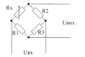
Figure 2 - Schematic diagram of the bridge measuring circuit.
In the figure, in the opposite arms of the bridge, the reference resistances R1, R2 and R3 are placed, as well as the measured resistance Rx, the platinum thermistor. To balance the bridge, it is necessary that the following relationship be realized:

If the equilibrium conditions of the measuring bridge are met, the voltage on its output diagonal will be absent, that is, 1 / pc = 0. If the measured resistance Rx changes, the equilibrium conditions of the measuring bridge will be violated and an appropriate electrical signal appears on this diagonal.
2.2 Justification of the choice of the density sensor
ESOOT implies the installation of a density sensor in the tanker compartment, which means that the sensor is not affected by environmental factors, but we need to ensure the necessary measurement accuracy. With these requirements, we select the necessary density sensor, namely the vibrational flow density meter NPC-P21.
The principle of the flow densimeter is based on measuring the vibration frequency of two vibrating tubes, through which the measured product flows. Frequency is listed by the processor in density (g / cm3)
Microprocessor electronic unit of vibration densimeter NPC-P21 provides statistical processing of data from the primary transducer and temperature sensor, indication of measured parameters on the built-in display.
For communication with an external automation, there is a current output (4-20 mA.), Which informs about the value of the density of the measured product. The main technical data are summarized in Table 2.
Table 2 - Technical characteristics of NPC-P21
| Working environment | Petroleum products, and other liquids. |
| Displays the parameters on the display | Density (g / cm2)3) |
| Temperature of the medium to be measured | From – 10 ° С to + 95 ° С |
| Density conversion range | From 0.6 to 2.0 g / cm3 |
| The basic error of the density conversion | 0,2 % |
| Temperature measurement step | 0,5 °С |
| Output analog signal | Constant current (4 - 20 mA) (0 to 5 V) With load up to 0.26 kOhm |
That is, we see that this sensor can introduce an error of 0.2%. Let's see how the volume will change with a decrease and increase in density by 0.2%.
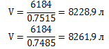
We will consider the same compartment of the gas tank truck with a volume of 8245 liters, with an average density of 0.75 g / m 3 . Previously, the weight of 6184 kg was determined.
We calculate how the density changes if the error is + 0.2%.
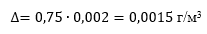
That is, the density will vary within ± 0.0015 g / m3.
We calculate how the volume will change if the density changes under the influence of the introduced error.
Determine the average deviation from the volume of 8245 liters.
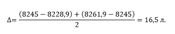
The error of our system should not exceed 50 liters. From this condition, we can say that we are satisfied with this sensor.
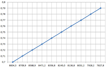
Figure 3 - Dependence of the volume of gasoline on density.
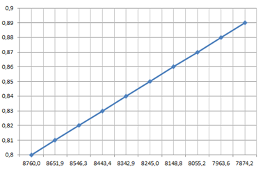
Figure 4 - Dependence of the volume of diesel fuel on density.
That is, we can conclude that the density measurement is necessary to control the volume of petroleum products.
Justification of the level measurement accuracy
The level is the most important among all the parameters of this system, because knowing the level, you can know the real volume of fuel using a calibration table or knowing the parameters of the fuel tank compartment.
The level measurement error should not exceed ± 1%, these requirements are set using corporate standards of the company, which say that the volume of fuel supplied to the filling station must have a maximum error of ± 50 liters.
2.3 Justification of the level sensor selection
ESOT means installing a level sensor in the tanker compartment, which means that the sensor is not affected by environmental factors, but we need to ensure the necessary measurement accuracy. From these requirements, we select the required level sensor, namely the capacitive level sensor LLS-AF 20310.
The basis of this type of sensor is the property of the capacitor to change its capacitance when changing the composition and distribution of the dielectric material that separates the plates of the capacitor.
The LLS fuel level sensor (LLS) is a high-precision instrument used to determine the volume of fuels and lubricants (gasoline, diesel, oil) in tanks of vehicles and other containers. It is used as a system for monitoring fuel consumption (control of drains and refueling), and systems of satellite monitoring of vehicles (GPS) of various manufacturers.
Also, the sensor can be used separately with the LLD indicator. On the principle of measurement, the LLS fuel level sensor is a capacitive type.
The sensor has a configurable analog output, with the output voltage independent of the supply voltage. The frequency output provides a frequency-modulated pulse signal, issued by a transistor output with an "open collector".
The analog and frequency outputs are protected against short circuits, improper connections and supply voltage
Table 3 - Characteristics of the LLS-AF level sensor 20310
Characteristic |
Value |
| Supply voltage, V | 7-45 |
| Power consumption, W | Not more than 0.6 |
Level change |
|
| Measurement period, sec | 1 |
| Relative reduced measurement error (in the temperature range from minus 60 to + 80 ° C),% | Not more than ± 0.5 |
Frequency output |
|
| Maximum frequency, Hz | 2000 |
|
- The lower limit is adjustable from 30 to 1900Hz - The upper limit is adjustable from 100 to 2000Hz |
|
| Load resistance to the frequency output, Ohm | At least 100 |
| Operating temperature range, ° С | From – 40 to +80 |
| Resistance of internal "suspender" to the pole of supply voltage, Ohm | 1500 |
That is, we see that this sensor can introduce an error of 0.5%. Let's see how the volume will change with a decrease and increase in the level by 0.5%.
We will consider the same compartment of the gas tank truck with a volume of 8245 liters, with an average density of 0.75 g / m 3 . The previously determined weight is 6,184 kg.
We calculate how the density will change if the error is + 0.5%.

That is, the level will vary within ± 41.2 liters. Thus, we can conclude that this sensor is suitable, because such an error is less than 50 liters.
This sensor has a frequency output with a square wave signal, so it is necessary to use a converter based on a single-shot device in order to obtain an analog signal at the output, namely the voltage depends on the frequency that will be fed to the microprocessor.
3. Output:
Thus it is clear that for the most accurate determination of the volume of petroleum products, it is necessary to know the data of all 3 sensors that are used in the electronic system.
List of references:
1.Измерения в промышленности: справочник: в 3-х кн., кн. 2: Способы измерения и аппаратура / Под. ред. П. Профоса. – [2-е изд., перераб. и доп.]. – М.: Металлургия, 1990. – 384 с.
2. Изъюрова Г.И. Расчет электронных схем. Примеры и задачи / Г.И. Изъюрова, Г.В. Королев, В.А. Терехов. – М.: Высшая школа, 1987. – 335 с.