
Abstract
Research and improvement of the method of high–precision leveling using digital levels
Content
- 1. The relevance of the research topic
- 2. Goals and objectives of research
- 3. The design and principle of counting digital levels
- 4. Reiki digital levels
- 5. Requirements for high–precision leveling
- 6. Measurement process
- 7. Conclusions
- Literature
1. The relevance of the research topic
The need to improve the method of high–precision leveling by the system "digital level – bar–code rake" is due to the fact that when performing this type of geodetic work on the results of measured excesses, various sources of errors have a significant effect, including the influence of vertical refraction of the surface layer of the atmosphere, bar–code racks, the charge of the battery, verticality of the slats.
In practice, the greatest application of the nature of the influence of vertical refraction of the surface layer of the atmosphere was obtained by the following approach: the effect of refraction is almost the same when taking the count on racks and the measured elevation at the level station, it is of an accidental nature. The residual effect of vertical refraction is weakened by leveling from the middle and the corresponding program of measuring the excess at the level station.
The existing normative documents specify the requirements for leveling taking into account the influence of refraction of the atmospheric surface layer, which include the time of the measurement, the height of the aiming beam above the underlying surface (the heel of the rack) and the program for taking the count on the rails. It should also be noted that the conditions for performing high–precision leveling in the field, in cities and on industrial sites vary significantly among themselves [1].
The main advantages of digital measuring technology over analogue are: rapid measurement, high accuracy, convenience of obtaining primary data and their automatic processing, as well as almost complete elimination of the "human factor", up to the achievement of the final result of the work. Digital (code) levels came to traditional optical levels. The basis for determining the excess of the digital level is the same principle as in the classical optical levels. However, instead of the usual rake, a special, "code", rake is used, and instead of the analyzer determining the position of the sighting axis of the level on the rack, not the person's eye, but a matrix photodetector. The operator's task is only to put the optical tube of the level on the rail, after which the recognition, processing and analysis of the image is automatically performed, and finally the output of the result [2].
Consequently, there is a need to conduct a number of studies on improving the methodology for performing high–precision leveling performed by the DL, which includes the study of the effect of vertical refraction of the surface layer of the atmosphere under various temperature regimes on measured excesses, as well as the improvement of the surveillance program on a leveling station. This is due to the fact that the principle of taking the readout of a DL on a bar–code rake differs from the principle of counting on metric racks by optical levels.
Of the numerous equipment of the company Sokkia should be noted high–precision digital level with autofocus SDL30 for leveling I class [3].
2. Goals and objectives of research
The aim of the research is to develop and
improve the method of high–precision leveling
performed by the system digital level –
bar–code rake
, taking into account the
influence of vertical refraction of the
surface layer of the atmosphere on its
operation.
Main goals:
perform an analysis of existing surveillance programs when performing high–precision leveling;
to carry out a study of the effect of the verticality of the rod when taking a report, on the accuracy of measurements;
to develop and investigate observational programs at the station during the leveling of I, II classes with the use of the DL;
Conduct approbation of the proposed techniques for high–precision leveling with the use of the DL;
analyze the effect of vertical refraction of the atmospheric surface layer on the results of the leveling of the central surface;
to carry out research on the effect of vertical refraction of the surface layer of the atmosphere on the results of a high–precision leveling of the DL;
to improve the method of high–precision leveling performed by the DL, taking into account the influence of vertical refraction of the atmospheric surface layer on the measurement results;
to carry out investigations of the influence of different illumination of bar–code rails on the results of leveling of the DL;
perform research on the effect of changing the capacitance of the secondary battery on the value of the change in counting on a bar–code rail.
The object of research is the measuring
leveling system digital level – bar–code rake
.
The subject of the research is the technique of performing a high–precision leveling of the DL taking into account the influence of vertical refraction of the surface layer of the atmosphere.
Scientific novelty consists in the following:
Investigations into the nature and magnitude of the effect of vertical refraction of the surface layer of the atmosphere on the measured excess of the DL;
Based on the results of the research, the technique for performing a high–precision leveling of the DL with the influence of the vertical refraction of the surface layer of the atmosphere was improved;
Method developed leveling I, II classes with the use of digital levels.
Methods of research. The theoretical base for carrying out the research is the model of the surface layer of the atmosphere, in which the viscous ray of the central nervous system extends, the methods of correlation, dispersion and regression analysis, elements of mathematical statistics, the theory of measurement errors, and methods for mathematical modeling of the results of practical measurements.
3. The design and principle of counting digital levels
Figure 3.1 shows the diagram of the NA 2002 level. Using the CCD receiver, the level code of the leveling rod is read. Optical elements of digital levels are mainly borrowed from ordinary levels, so it is possible to visualize the rake. When measuring in automatic mode, the images of the code scale strokes of the slats through the beam splitter block are projected onto the sensitive area of the CCD receiver [4].
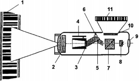
(1 – barcode leveling rake; 2 – the lens; 3 – focusing component; 4 – sensor of the position of the focusing component; 5 – compensator block; 6 – the block of the control of position of the compensator; 7 – beam splitter unit; 8 – a grid of threads; 9 – eyepiece; 10 – CCD receiver; 11 – the image of the code of the leveling rod.)
The beam–splitting unit divides the incident radiation in the spectral region into infrared and visible. While the radiation lying in the infrared region of the spectrum is reflected from the beamsplitter face toward the receiver, the visible part is freely passed by the beam splitting unit and forms the image of the strip in the plane of the filament grid. Due to this, on the one hand, the observer does not perceive a loss in the power of light, and on the other hand, radiation of sufficient intensity falls on the sensitive area of the CCD receiver, which has a high sensitivity in the infrared region of the spectrum. The CCD receiver consists of 256 photosensitive elements (pixels), the distance between which is 25 ?m. The optical system of the level has a field of view equal to 2 °, so that with a minimum viewing distance of 1.8 m, a sensitive section of the CCD receiver is projected onto a section of a 61 mm long strip, and at a distance of 100 m – 3.5 m.
When the telescope is refocused in the range from 1.8 m to 100 m, the focusing component moves to. Knowing the position of the focusing component, you can roughly calculate the distance to the rack.
The distance to the slats and the position of the focusing component are connected. The position of the focusing component is recorded by an electronic position transmitter. During measurements by the electronic system, the tilt of the device, or more precisely, the deflection of the compensator's sensitive element, is tracked. The CCD receiver converts the image of the code strokes into an analog video signal, the video signal is amplified and converted to digital. A microprocessor with 256 pixels of the CCD receiver receives a discrete signal having 256 gradations of brightness.
The functioning of the digital level is based on the principle of correlation. At the same time, the bar code written in the device's memory is compared with the signal generated by the CCD receiver (Figure 3.2). When applying correlation in digital levels, two parameters are optimized, namely, height and scale.
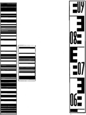
device–rakeis represented as the offset of the strokes of the rake code, on the other hand the scale of the image of the code strokes is changed as a function of the
device–rakedistance [5].
4. Reiki digital levels
Digital levels differ in principle from reading on the rack, and racks – the bar codes used for this purpose. Therefore, working with the level of Leica Geosystem AG, it is necessary to use rails designed for the levels of this company only, working with the TOPCON level of TOPCON rails, etc. The quality of the material of the rails used for measurements depends on the average square error of the excess measurements the level of 1 km of double stroke. Firms–manufacturers aspire to achieve not only high accuracy of measurements, but also to make rejki easy and strong. Today, a new material has appeared – fiberglass (fiberglass), which has an excellent strength and weight ratio and a small coefficient of linear expansion of –10 ppm (mm / km).
Usually, on one side of the rack, a binary code is placed for automated counting, and on the other side – a normal scale for visual counting [6].
5. Requirements for high–precision leveling
Geodynamic polygons are divided into:
local polygons, timed to active deep faults and ruptures of the earth's crust;
area, covering areas of possible epicenters of destructive earthquakes, areas of large settlements and areas of operated and under construction hydroelectric stations;
regional, linking large geological structures.
Table 5.1 required accuracy
|
Leveling class |
Mean square error |
Admissible discrepancy in polygons and along lines, mm |
|
|
Accidental, mm / km |
Systematic, mm / km |
||
|
I |
0.8 |
0.08 |
3мм√L |
|
II |
2.0 |
0.20 |
5мм√L |
|
III |
5.0 |
– |
10мм√L |
|
IV |
10.0 |
– |
20мм√L |
On local and area polygons, high–altitude networks are created in the form of intersecting lines of leveling I and II classes.
High–altitude networks on local and area constructions are connected to the main high–altitude basis of Russia for obtaining heights in a unified system. The leveling network in this case is regarded as free, based on one reference of the state level network.
High–altitude networks of regional constructions are included in the network of state leveling of I and II classes.
The requirements for the leveling method, levels and slats, the order of sampling at the station are the same as for the production of the state leveling of the corresponding class.
When fixing lines on geodynamic polygons, they prefer rock and wall frames.
All old benchmarks and non–working wells located at a distance of 0.5 km from the line of the leveling line I class and at a distance of up to 1 km from the line of the second class line are necessarily tied to them, respectively, leveling I or II classes.
A mark is used to weld a non–working well, which serves as a century reference. If there are no such wells at the site, then a century–old benchmark is laid. On the site at a distance of 30 – 70 m from the age–old benchmark, all types of soil centers and benchmarks used at this landfill are laid. Twice a year (winter and summer) level all the benchmarks on the site and compare the excesses obtained. The types of frames, obviously unstable, are excluded from further leveling.
Leveling of I and II classes on geodynamic and technogenic polygons is part of a complex of scientific geophysical studies that serves to obtain quantitative characteristics of deformations of the earth's surface. Therefore, measurements are performed in several consecutive cycles. The time interval between the re–leveling is established proceeding from the expected velocities of modern vertical movements of the earth's crust.
When designing leveling networks on man–made landfills, the distance between the boundary of the deposit and the benchmarks considered immobile should be taken equal to the 8–fold depth of the lower exploited horizon, but in all cases not less than 6 km. The designed lines are laid in the form of networks or separate lines. Not less than four points (benchmarks) of the perimeter of the leveling polygon coinciding with the contour of the deposit, lay the way to the frames, which are considered fixed [7].
6. Measurement process
To start measuring the leveling from the middle,
the level is set in the middle between the points
T1 and T2, bring it to the working position,
select the appropriate program in the device.
We set the slats to points T1 and T2, keeping
them strictly in level. The observer performs
the aiming of the telescope on the rail and
focusing. After pressing the start
button
on the body of the level, the measuring
process proceeds in automatic mode. The
readings from the position sensor of the
focusing component are automatically read,
the position of the compensator's sensing
element is determined, depending on the
intensity of the signal, the integration
time is determined to achieve the required
level of saturation of an individual CCD
pixel, coarse and precise optimization is
performed [8].
7. Conclusions
Upon completion of the master's thesis, the following results should be obtained:
a technique for high–precision leveling with the use of new tools – digital levels;
programs of observations at the station during the leveling of I and II classes;
the methodology for performing the research and the results of the effect of vertical refraction of the surface layer of the atmosphere on the DL;
Improved methodology for leveling I and II classes, taking into account the features of the influence of vertical refraction of the surface layer of the atmosphere on the results of measurements of exceedances of the DL;
the results of studies of the influence of different illumination of bar–code rails on the results of measurements of excesses at the DL station and ways of weakening this influence;
results of studies of the effect of reducing the capacitance of the secondary batteries on the magnitude of the change in the count over the bar–code rails.
results of the influence of the verticality of the rail when taking a report, on the accuracy of measurements;
Literature
- Н. М. Рябова. Исследование и совершенствование методики нивелирования I и II классов с применением цифровых нивелиров. – Новосибирск, 2013.– 176 с.
- Г.В. Колесников, М.В. Киселев некоторые аспекты измерения превышений методом анализа штрих–кода//Геопрофи.– 2008.– № 1.
- В.В. Грошев и М.С. Романчиков. INTERGEO 2008 тенденции и перспективы дальнейшего развития технологий // Геопрофи.– 2008.– №5
- О.В.Евстафьев. Нивелиры – от оптических до электронных// Геопрофи.– 2003.– № 1
- Карсунская М.М. – Геодезические природных ресурсов, 2002. – 186с.
- Соболева, Е. Л. Совершенствование технологии нивелирования II класса с использованием цифровых нивелиров / Е.Л. Соболева // Современные проблемы геодезии и оптики: сб. науч. ст. / СГГА. — Новосибирск, 2006.
- Инструкция по нивелированию I II III IV классов. ГКИНП(ГИТА) –03–010–03.2004.– М.: ЦНИИГАиК,2004.– 226 с.
- Уставич, Г. А. Технология выполнения высокоточного нивелирования цифровыми нивелирами / Г. А. Уставич // Геодезия и картография.– 2006.– № 2.