
Abstract
Contents
- Introduction
- 1. The concept of a three-axis stabilizer
- 2. The purpose and tasks of work, the required results
- 3. Device Development
- Conclusion
- References
Introduction
The modern level of automation of production processes is closely related. with microprocessor technology. Automatic control system based on industrial programmable controllers that perform regulatory functions electric drive, interrogation of sensors, formation of control action, provide communication between the system and its internal elements and nodes, data output.
1. The concept of a three-axis stabilizer
The stabilizer for video filming in motion or steadicam (eng. Steadicam), there is a device designed for making video in motion. Since the time of creation, steadicam has become an indispensable auxiliary camera equipment, it allows you to get a stable picture when the operator moves on the video filming site without shaking and deviations from the horizon or a given point of video filming.
Stedicam was invented in 1976 by cameraman Garrett Brown, and
as the device was patented in 1977 under the name Equipment for
use with hand-held movie cameras
. In the aftermath, picking up
the popularity of the cameraman-inventor in 1978 received an Oscar for
technical advances. [1]
Mechanical steadicam based on the principle of damping vibrations cameras with balances and loads. This paper presents electronic steadicam whose principle of operation is to manage DC motors mounted on a special frame.
A general view of the stabilizer along three axes is shown in Figure 1.1.
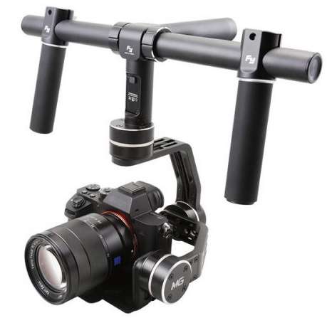
Figure 1.1 – General view of the stabilizer
2. The purpose and tasks of work, the required results
Based on the topic of work, we can make a simple conclusion that the development of a three-axis stabilizer requires the following steps:
- To determine the constituent elements of the stabilizer
- Assemble the supporting frame
- Implement control algorithm based on STM32F4
- Spend debugging of the drive PID controllers
- Achieve the highest possible quality of the camera stabilization
3. Device Development
Stabilizer components
STM32F4 Discovery debug board
In the manufactured device used debug board STM32F4 Discovery on the basis of the microcontroller STM32F407VG, with which the initialization is carried out sensor GY-521 and the conversion of the obtained values and engine control DC through driver L298N.
A general view of the board is shown in Figure 3.1.
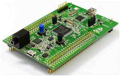
Figure 3.1 – General view of the debug board
DC motor
DC motor – there is an electric machine that converts DC electrical energy into mechanical energy. There are engines unipolar, collector and brushless execution. In that work collector DC motor is used, the general view of which is presented in Figure 3.2.
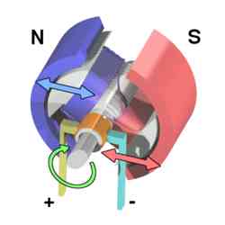
Figure 3.2 – General view of a DC collector motor
L298N Engine Driver
To control DC motor, the dual-channel driver L298N is used, which consists of two H-bridges, made on the basis of transistors and shunt diodes, to provide reverse conduction. General view of the driver L298N presented on Figure 3.3.[3].
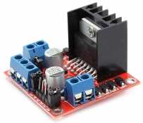
Figure 3.3 – General view of the driver L298N
GY-521 module
The MPU-6050 chip is the main element of the GY-521 module. MPU-6050 contains three axial MEMS gyroscope with 16 bit ADC, three axial MEMS accelerometer with 16 bit ADC and temperature sensor. The module contains all necessary you need to connect the microcircuit and stabilizing the supply voltage 3V [4]. The module also contains SMD pull-up resistors for the I2C bus, module power indicator as well as a power indication LED. General view of the module presented in Figure 3.4.
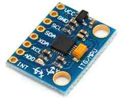
Figure 3.4 – General view of the module GY-521
Supporting frame
It should be noted that the design on which the equipment will be installed plays a big role in the mechanism. It is very important to achieve structural rigidity, while minimizing weight, as cumbersome and heavy steadicam would be inconvenient for use.
Thus, parts were made for fastening engines to aluminum profiles, corner joints between profiles and strips (Figure 3.5).
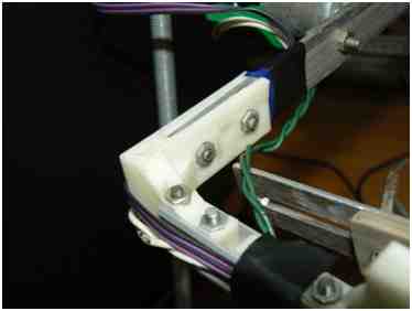
Figure 3.5 – Printed detail
The algorithm of the device work.
The projected device is a positional system electric drive with three DC motors controlled with using the L298N drivers which are controlled from the STM32F4 debug board.
The automatic engine control system consists of one contour with closed feedback position in space by sensors located in the MPU-6050.
For convenience, we will present the control system in the form of a single engine control loop (Figure 3.6).
Figure 3.6 – Engine control system
(animation: 6 frames, 10 cycles of repetition, 10.7 kilobytes)
(x – reference signal, e – mismatch signal, u – controller output signal;
g – perturbing effect;
y – the actual position of the OR; m – measurement noise;
f – feedback data on the position)
Connecting the device to the power, the program starts running into the microcontroller. Peripheral initialization occurs during the program microcontroller, also setting up data transfer protocols with sensor and the board starts the cycle of initialization and configuration of the MPU-6050. After performing the steps described above, and in the case of successful sensor initialization, the controller includes in the program a continuous cycle of reading and processing data from six axes of the module with subsequent calibration and conversion of values for output control signals to drivers L298N.
Sensor Signal Filtering.
When working with MEMS sensors, especially with accelerometers, signal filtering is necessary to improve the quality of regulation due to their high sensitivity. Thus, in the presented work was a simple complementary filter was used (Figure 3.7).
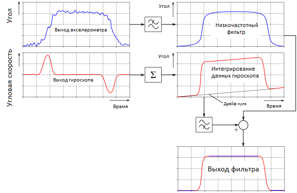
Figure 3.7 – Complementary Filter Algorithm
Conclusion
3D stabilizer is a device for video filming in motion in order to obtain high-quality pictures and a smooth frame transition. The device has a constructive possibility of balancing the camera to reduce the effect of angular loads. Also steadicam are easily reprogrammed using the MATLAB software package and contribute adjustments to the work of the position regulators in real time, which is enough handy when debugging the system.
The device can also be considered a stand for operation with a positional electric drive, on which can be practiced with the adjustment of the PID position controller and also see the result of the settings.
As a result of the development, a 3D stabilizer was assembled for video filming in motion, with the completion of which get a ready-made device, not inferior to the serial, and most importantly much cheaper.
This master's work is not completed yet. Final completion: May 2019. The full text of the work and materials on the topic can be obtained from the author or his head after this date.
References
- Steadicam. [Электронный ресурс]. – Режим доступа: https://ru.wikipedia.org/wiki/Steadicam.
- Отладочная плата STM32F4 Discovery. [Электронный ресурс]. – Режим доступа: http://robotosha.ru/stm32/…
- L298 Dataseet – STMicroelectronics. DUAL FULL-BRIDGE DRIVER L298.
- MPU-6000 and MPU-6050 Register Map and Descriptions Revision 4.0, DataSeet №RM-MPU-6000A-00.
- MPU-6000 and MPU-6050 Register Map and Descriptions Revision 4.0, RegisterMap №RM-MPU-6000A-00.
- МЭМС-датчики движения от STMicroelectronics: акселерометры и гироскопы. [Электронный ресурс]. – Режим доступа: http://www.russianelectronics.ru/leader-r/review/…
- STMicroelectronics. [Электронный ресурс]. – Режим доступа: https://www.st.com/content/st_com/…
- Системы регулирования положения. [Электронный ресурс]. – Режим доступа: https://studfiles.net/…