
Abstract
Content
- 1. Hand anthropomorphic robot.
- 2.Programmable charge.
- 3.Used motor for elbow joint.
- 4. Fasteners for the engine of the elbow joint.
- 5.A similar way to control.
- 6.Findings
- References
1. Hand anthropomorphic robot.
In the new work is the creation of the hand of anthropomorphic work. In contrast to the past device, this will have not only the wrist joint, but also the elbow and forearm. At the moment, the main task is to study the structure of the human hand and the creation of its analogue using modern technologies. The structure of the human hand is quite complicated, which complicates the creation of its analogue. The development of such a device is quite a significant contribution both to science and to human life. Most prostheses are made abroad, which increases their cost, which is already quite large. At the moment there are several types of prosthetic hands, namely: cosmetic and functional. The main function of cosmetic prostheses is to recreate the appearance of the human hand. At the same time, a functional prosthesis does not have the same beautiful appearance as a cosmetic one, but it provides several basic functions, such as grip. Functional prostheses are also divided into workers, traction and myoelectric. The highest cost of myoelectric (bionic), as they are the most modern. But not all anthropomorphic robots are used as prostheses. They have been widely used in areas where it is necessary that the control of some technological process is carried out by the operator remotely, for example, in aggressive environments, in space, or simply in places difficult to reach for humans.
For this bioelectric model of the hand, the control method was selected using an electromyographic sensor. In order to understand how this sensor works, you need to familiarize yourself with how the human hand works, which will also help with the design of the arm design of an anthropomorphic robot itself.
The electromyographic sensor is a sensor that removes the electromyogram from the muscles of the operator. Most often, the information is removed using three electrodes, which are located on the hand of the operator. In addition to the three electrodes, the sensor includes a special driver that recognizes the received signal, processes it, and transmits it to the software board.
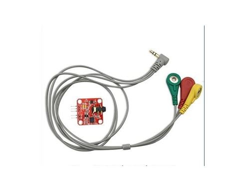
Figure 1 – Electromyographic sensor.
But this information received from the sensor needs to be reprocessed and transmitted to the drive, in order to perform some kind of action, movement. The process of removing information using this sensor is quite complicated. Electrodes must be installed in such a way that one of them is located in the middle of the measured muscle, the second – at its end and the third – on the arm that has no muscle, i.e. on the bone of the elbow joint. Information captured with this sensor may also be inaccurate, so a bunch of actions are required to process the signal, such as cutting off noise. It is required to process both a false and a useful signal and be able to distinguish them. This sensor removes information not only about the elbow and shoulder joint, but also the hand. Every movement is a different impulse. When you configure this sensor, you need to learn to distinguish the signals that come to the board. An example of connecting the sensor to the board and the operator’s hand itself can be seen in the figure below (fig.). The appearance of noise and inaccuracies when removing a signal using this sensor is also influenced by a number of factors that also need to be taken into account, namely: when installing sensors on the operator’s hand, it is necessary to clean it with alcohol or some other substance similar in chemical properties on the skin of the electrodes, and the electrodes themselves at the point of application. If we neglect this, then the removed signal may appear with a large amount of noise, and not appear at all.
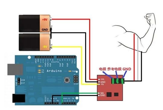
Figure 2 – Connecting electromyographic sensor.
The STM32F4DISCOFERY board will be used to process this information and transfer it to the drive. The choice fell on this board, as it has a wider functionality and technical characteristics when compared with the board that was used in the previous project, namely Arduino Deumilanove.
2.Programmable charge.
The STM32F4DISCOFERY [ 10 ] board will be used to process this information and transfer it to the drive. The choice fell on this board, as it has a wider functionality and technical characteristics when compared with the board that was used in the previous project, namely Arduino Deumilanove.
This board also has a huge number of characteristics, we give them the main:
* 32–bit ARM–microcontroller STM32F407VGT6 of the Cortex–M4 family (Frequency: up to 168 MHz. Program memory (Flash): 1 MByte. RAM (RAM): 196 KB. Debugging via JTAG or SWD).
* The ST–Link / V2 debugger and programmer for debugging and flashing the STM32F407VGT6 microcontroller is located on the STM32F4DISCOVERY board and it is possible to switch it to programming and debugging of other boards and controllers. through the withdrawn SWD connector and jumpers.
* Outputs for external power supply + 5V and the possibility of powering other devices from +5V и +3V.
* Microcontroller RESET Button STM32F407VGT6.
* Four LEDs and one button available for programming
3.Used motor for elbow joint.
In this project, the Namiki 22CL–3501PG engine will be used to implement the movement of the elbow joint. The choice fell on this engine, as it has a fairly low cost and can provide good performance. The Namiki 22CL–3501PG is a DC motor with a built–in encoder.
Datashit this engine:
* Brand: Namiki Coreless Motor (Japan)
* Model: 22CL–3501PG
* Operating Voltage: 12VDC
* Rated power: 15W
* Stall torque: 16.5kg*cm
* Continuous torque: 5kg*cm
* Diameter: 22mm
* Shaft length: 19mm (with 90–degree double–cut)
* Length: 65mm (includes encoder gear box)
* Stall current: 1.8A
* Reduction ratio: 80:1 (metal planetary reduction gear)
* Output speed: 120 RPM@12VDC
* Weight: 140g
4. Fasteners for the engine of the elbow joint.
At the moment, a 3–D model was designed for mounting this engine and recreated using a 3–D printer located in the department. For printing using ordinary ABS plastic.
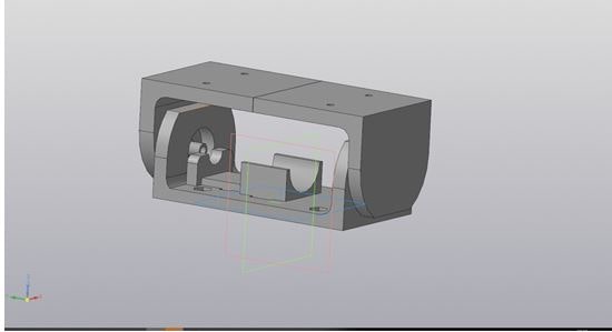
Figure 3 – Engine Engineered Part.
This design allows you to rotate the elbow joint 180 degrees, which is quite an important aspect in the management.
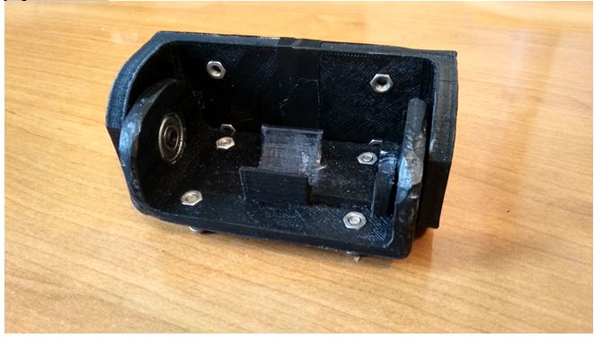
Figure 4 – The recreated part of the engine mount elbow joint.
5.A similar way to control.
Control of the elbow joint is also possible with a flex sensor (Flex sensor). The principle of operation of the sensor is quite simple. It is based on a photoresistor and a super-bright LED that are located at opposite ends of the silicone tube. The light enters the photoresistor through this tube and, depending on the flow of light coming into the photoresistor, it changes its resistance at the output. The signal coming from the sensors comes to the software board, is processed and fed to the servo, which in turn begin to move and bring the fingers of the robo-arm into motion. This sensor is very sensitive, therefore, in order to use it in a project, it is required to implement signal filtering. There are two ways to accomplish this task: software and hardware. The easiest way is software implementation. Since these sensors have already been used in previous work, you can also use ready-made software-implemented filters.
Figure 5 – 3D model of the fastening part for the engine of the elbow joint
(animation: 10 frames, 7 repetition cycles, 220 kilobyte)
6.Findings
- In this paper, the developed robo–arm imitating movements, which are performed by an operator with a touch glove, was presented.
- This device is used as a prototype for creating anthropomorphic robots, as well as remote control systems in hard-to-reach places, prostheses.
- In this paper, the topic of creating electromechanical prostheses is investigated, the elbow part of the bionic arm device is developed and implemented. The study design has been modernized and recreated [ 10 ]. The structure of the human hand was analyzed, as well as the methods for controlling the elbow joint of an anthropomorphic robot arm.
References
- Программирование Ардуино [Электронный ресурс] : Справочник языка Ардуино, Украина, [2003]. URL: http://arduino.ua/... (дата обращения: 30.11.2016).
- Программирование Arduino –; библиотека Servo [Электронный ресурс]: сайт создания роботов , 29 мая 2010. URL : http://robocraft.ru/...(дата обращения: 30.11.2016).
- Роботизированная рука с использованием Arduino [Электронный ресурс]: блог сайта Arduino, США, 24 июня 2014. URL : https://blog.arduino.cc/... (дата обращения: 01.12.2016).
- Использование датчика Flex [Электронный ресурс]: Проект сайта sparkfun.com, США. URL : https://learn.sparkfun.com/... (дата обращения: 20.11.2016).
- Гринь В.В., Басалыгин Е.В., Розкаряка П.И. Разработка аппаратной части Робо–;руки на базе платы Arduino / Международная научно–;практическая конференция ИННОВАЦИОНЫЕ ПЕРСПЕКТИВЫ ДОНБАССА // Перспективы развития электротехнических, электромеханических и энергосберегающих систем, 2017. –; 230–;233с., [Электронный ресурс]. Режим доступа: http://ipd.donntu.ru
- Определение сервопривода [Электронный ресурс] . Режим доступа: http://dic.academic.ru/...
- Рука и предплечье [Электронный ресурс]: Проект сайта inmoov.fr, США. URL : http://inmoov.fr/... (дата обращения 16.01.2017).
- Виды протезов рук [Электронный ресурс]. Режим доступа: : http://motorica.org/... (дата обращения 14.04.2018).
- Бионический протез руки [Электронный ресурс]. Режим доступа: : http://mech.spbstu.ru/... (дата обращения 14.04.2018).
- Разработка и анализ функционального протеза руки с нейрофизиологической системой управления [Электронный ресурс]. Режим доступа: : https://boomstarter.ru/... (дата обращения 14.04.2018).
- Строение руки человека [Электронный ресурс]. Режим доступа: : https://www.eurolab.ua/... (дата обращения 14.04.2018).
- Плата STM [Электронный ресурс]. Режим доступа: : http://firsthand.ru/... (дата обращения 14.04.2018).