
Content
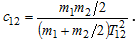
- 1. Control object description
- 2. Damping methods
- 2.1 With corrective feedback and without
- 2.2 With the optimization of a modular optimum
- Conclusion
- References
- 2.2 With the optimization of a modular optimum
2. Description of the Сontrol object
The object of control - the mechanism of movement of the gantry crane bridge .
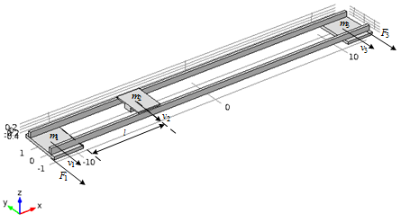
Figure 1 – Сontrol object
To simplify the scheme, we present the bridge in the form of two solid metal profiles with a cross section of rectangular shape and reduced density, and the understated value of the elastic modulus of the material so that the weight of the structure approximately corresponds to the real data. Next, we place the trolley in the middle of the bridge and apply an effort to the extreme parts of our design, which corresponds to the acceleration of the bridge to a speed of 0.5 m/s for 1 s when working out the trapezoidal law of speed change.
Changes in the speeds of the extreme points of the bridge v1 and the trolley v2, which is at its midpoint, are shown in the graphs Fig.2. It is clear that the point of the design is carried out undamped oscillations, which gradually degrade the strength and subsequently can cause the release of the crane from the building, as well as injuries of employees.
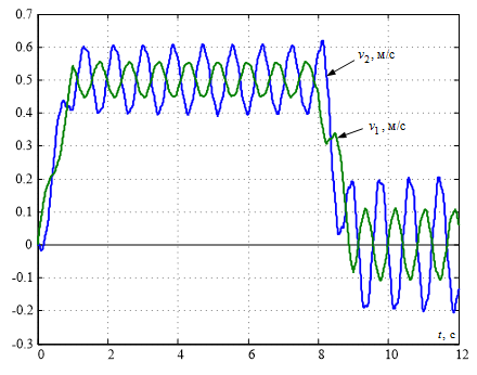
Figure 2 – transient processes of motion velocities of the elastic structure of the bridge crane
To suppress undamped oscillations, it is necessary to synthesize an appropriate control system for the speed of the bridge movement, for this it is necessary to have a linear mathematical model of the controlled object.
The mathematical model of the object can be made on the basis of kinematic schemes of multi-mass systems (shown in Fig. 3)
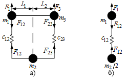
Figure 3 – Kinematic model of the bridge
In Fig.3а and the bridge is presented in the form of three concentrated mass – extreme points m1 and m3, connected by elastic bonds with the stiffness coefficients C12 and C23 with the point m2, in which the trolley is located.
If you place the trolley in the middle of the bridge (L1=L2), the stiffness coefficients of the elastic bonds must be set the same. If at such arrangement of elements equal to each other, and the masses are concentrated at the ends of the axle, and attached to them strength, at the same distance from the supports, the mass of which are equal, then the kinematic pattern of our control object can be simplified to a two-mass, leaving one leg and the center point, the weight of which should be reduced in 2 times. The kinematic scheme for this case is shown in Fig.3b. Its mathematical description will look like this:
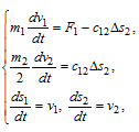
where F1 is the force applied to the first mass, F12 is the elastic force, Δs2=s1-s2 - is the elastic deformation value.
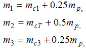
Where:
So, using some simplifications, we transformed a complex three-hour kinematic system into a simpler two-mass model, which will be much easier to conduct experiments and implement a control system to extinguish elastic oscillations.
2. Damping methods
2.1 Comparison of the system of subordinate speed control without corrective feedbacks.
Having an approximate model of the controlled object, we synthesize a speed control system. To control the drives of the wheels of the bridge, we use a system of subordinate speed control. The current loop expressed in the form of aperiodic link with time constants Tt.
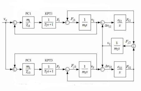
Figure 4 – Block diagram of the subordinate speed control system of a three-mass open system object.
Take the following values T=4ms, TC1=TC2=2 T. Assume that the length of the bridge L=20 m, and the trolley is located at a distance l=8 m from the left edge of the bridge, where the mass m1. Get the following graphs:
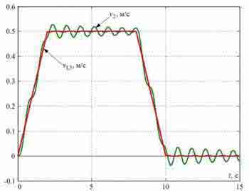
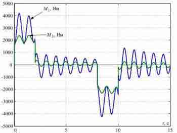
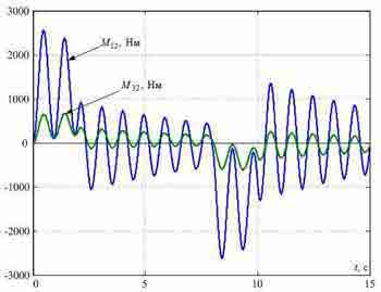
Figure 5 — Transients in a typical SPRS synthesized without taking into account the elasticity of metal structures.
On the charts you can see-the elastic vibrations slowly fade. They can be reduced by adding corrective feedbacks of two masses wound up at the input of the regulator:
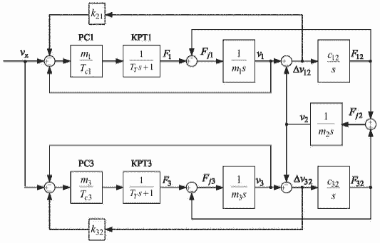
Figure 6 – Block diagram of the system of subordinate speed control of a three-mass object with a closed system
Taking into account the elasticity of metal structures:
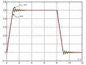
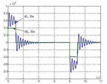
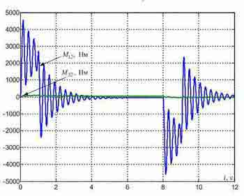
Рисунок 7 — Transients in the standard SPRS synthesized taking into account the elasticity of metal designs.
2.2 The system of subordinate speed control with corrective feedbacks on the speed differences of the moving masses with the optimization of closed speed circuits by the modular optimum
The next method of damping elastic vibrations in two-mass systems is the introduction of feedbacks to determine the difference in the velocity of the masses with the optimization of closed-loop velocity of the modular optimum.
First, consider the block diagram of the three-mass system Fig.8, where F1, F2, F3 – the force generated by the drive motors of the wheels; F12 F32-elastic forces of interaction are concentrated masses, c12, c32-elasticity coefficients; v1, v2, v3-the speed of the points at which the masses m1, m2, m3 are located
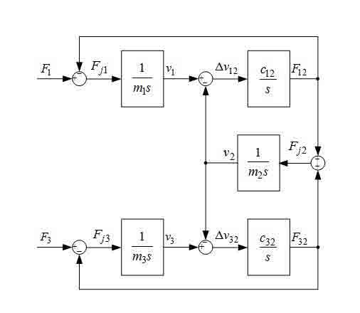
Figure 8 – Block diagram of the three-mass system
The system uses two electric drives; therefore, it is necessary to determine two time constants for the speed regulators and two feedback coefficients.
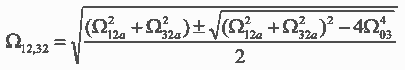
Optimize the closed loop speed will be modal optimum. We write the transfer function of the job at the speed of the speed of the second mass:
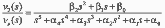
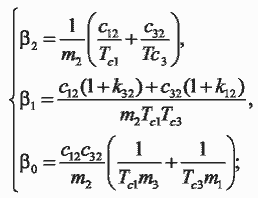
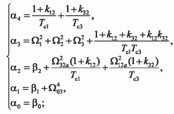
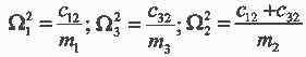
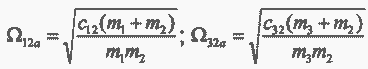
– oscillation frequency of moving masses;
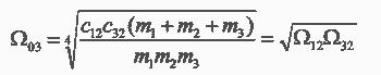
– root of the characteristic polinomial of a three-mass system;
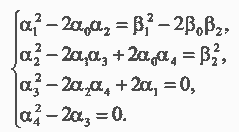
For a start, you can use the values of feedback coefficients and time constants that we obtained when optimizing two-mass systems.
We investigate the process of damping elastic vibrations. Take the following parameters of the control object m1 = m2 = m3 = 20, c12 = 4000, and c32 = 2 * c12. The result is visible in Fig.9 a). We also calculate the parameters for such values 1) m1 = 5kg m2 = m3 = 20kg, c32 = 2 * c12; 2) m1 = 60kg, m2 = m3 = 20, c32 = 2 * c12. The result is in Fig.9 b), c).
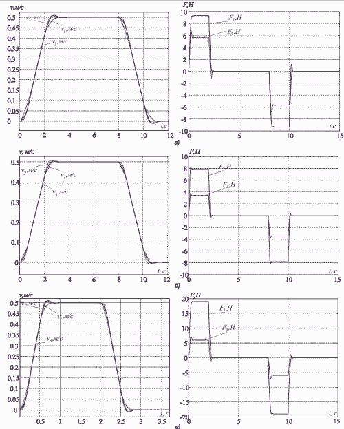
Figure 9 –Schedules of transient processes of the subordinate regulation system
As can be seen in the graphs, in all cases the elastic vibrations are successfully damped. Transients vary slightly, there is an overshoot to 10% which is acceptable. Thus, this method of damping effectively suppresses elastic oscillations in a wide range of ratios of moving masses and frequencies of elastic oscillations.
We will implement the vibration elimination system in the software package for dynamic modeling of SimInTech technical systems. The main areas of use of SimInTech are the creation of models, the design of control algorithms, their debugging on the object model, followed by the generation of source code in C for programmable controllers. In particular, the project uses the controller STM32f407VET6. The clocking frequency is 168 MHz, Flash memory is 512 Kbytes, 128 Kbytes of SRAM memory. The performance of this controller is enough for our tasks. Also, in addition to the controllers, we need a 3-axis accelerometer to receive feedback from the moving masses.
Conclusion
- Толочко О. І., Коцегуб П. Х., Федоряк Р. В. Дослідження впливу середньогеометрічного кореня характеристичного полінома на властивості системи модального керування двомасовим електромеханічним об‘єктом // Наукові праці ДонДТУ. Серія „Електротехніка і енергетика”. – Донецьк: ДонДТУ. – 2002. – №41. – С. 146-155
- Александров Е. Е., Кузнецов Б. И., Радиевский А. Е., Тернюк Н. Э. Оптимизация электромеханических систем с упругими связями. – Харьков: IMIC, 1995. – 304 с
- Коцегуб П. Х., Баринберг В. А., Толочко О. И., Федоряк Р. В. Оптимизация двухмассовых систем регулирования скорости // Известия вузов. Электромеханика. – 1998. – №4. – С. 54-57.
- Божко В. И. Бажутин Д. В. Подавление упругих колебаний в трёхмассовых электромеханических системах путем введения корректирующих обратных связей по разностям скоростей движущихся масс Перспективы развития электротехнических, электромеханических и энергосберегающих систем – 2016/ Материалы II международной научно-технической конференции студентов, аспирантов и молодых ученых. – Донецк, ДонНТУ – 2016, Том 2, с. 235-238
The SCS, synthesized without taking into account the elastic connections damps the oscillations very weakly;
SCS with additional corrective connections for the velocity difference effectively damps elastic oscillations, although it differs by a slightly higher overshoot by the total elastic moment and the presence of a small overshoot in speeds. The main advantage of this system is the simplicity of its implementation, since All feedback signals are easily measured.