
Abstract
Content
- Introduction
- 1. Relevance of the topic
- 2. Object and purpose of the study, planned results
- 3. General provisions on PPCS
- 3.1 Appointment of PPCS
- 3.2 Classification of PPCS
- 3.3 Vertical control principle
- Summary
- Source list
Introduction
The tremendous development of all industries depends on the level of automation of production. Automation of production requires sources of mechanical energy of different capacities. In large-scale industries as sources of mechanical energy are electric motors. One of the first invented engines, but still relevant, is a DC motor.
1. Relevance of the topic
Most industries to perform complex manufacturing processes together with the engine is necessary and the control system of the engine or engines performing the same job. This system provides different mechanical performance and provides the engine with the desired output parameters (torque and speed of the motor shaft). To control a DC motor, a thyristor Converter and a control system are used. The control system of the thyristor Converter of the DC motor is called pulse phase because of the principle of its operation. The aim of this work is the creation of a full-fledged PPCS on the basis of the Board STM3F4, which will provide a wide range of control PTA.
2. Object and purpose of the study, planned results
The Object of development and research is a three-phase non-reversible thyristor DC Converter executed on the bridge circuit.
The Purpose of – the development of a pulse-phase control system three-phase non-reversible thyristor DC Converter executed on the bridge circuit on the basis of the Board STM32F4. The developments were carried out on the basis of lectures on thyristor Converter control systems. The work is performed using mathematical modeling methods. The simulation of the pulse-phase control system by a three-phase non-reversible thyristor DC Converter executed on the bridge circuit with the use of the software package Matlab and its main complement Simulink is carried out. As a result, a model of the pulse-phase control system of a three-phase non-reversible thyristor DC Converter executed on the bridge circuit is developed
3. General provisions on PPCS
Power electronic devices consist of a power part and a control system (CS). The power part includes electrical circuits and elements that are directly involved in the transmission of electrical energy from the primary source to the consumer. Sometimes these chains together with power elements are called the main ones, as they determine the main technical and economic indicators of the power electronic device and, first of all, its efficiency. The power part of the device is the power Executive body that determines the main functions of the Converter. For example, the power part of a single-half-wave thyristor rectifier consists of one thyristor and electrical connections that provide its connection to the switched electrical circuit. Taking into account the determining influence of the power part on the technical and economic characteristics of the device as a whole, its study is given the main attention. For the operation of power transistors, thyristors and other devices they need to submit the appropriate control signals. These signals are generated by the control system, which processes and outputs information, as well as generates control pulses of electronic keys of the power part of the circuit. Therefore, SU consists of elements and functional units associated with the processing of information flows and the formation of control pulses. At the same time, the energy consumed by SU tends to minimize as much as possible. The control system also includes elements and components that provide current monitoring of the device as a whole, fault diagnosis and management of protective devices.
Figure 1.1 highlights some function blocks in the generalized block diagram. The d sensors unit contains sensors of adjustable and controlled parameters. As is usually governed by output parameters, the sensors are directly included in the feedback channel regulation. Signals from these sensors come to the REG controller, which functions include the formation of the control law of the power part elements.
The pulse generator of FIU control is a matching device between the inputs of power devices and the output of the regulator. The pid block generates control impulses, directly to the incoming power components. Controller signals are low power signals and do not meet the requirements for control pulses of power devices (thyristors, transistors, etc.).
Pulse driver control, functionally, and often structurally complete device, also called driver
(drive – drive).
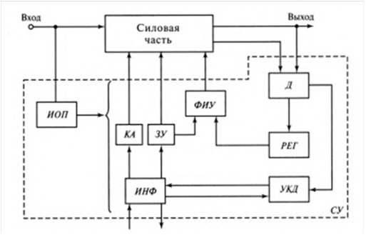
Figure 1.1 Generalized block diagram of the control system
3.1 Appointment of PPCS
The system of pulse-phase control (PPCS) of the Converter device is designed to generate and distribute control pulses of a certain duration and shape, distribute them to the corresponding phases in multiphase systems and change the moment of supply of these pulses to the control electrodes of the thyristors of the Converter. In the Converter devices are used semi-controlled power semiconductor devices (PSD) – thyristors, triacs, fully controlled PSD - lockable thyristors GTO, IGCT, and IGBT transistors. The main task of the PPCS is to convert the analog signal into pulse control signals by angle, regulation of the average rectified voltage Of the UTP thyristor Converter (TC) depending on the level, polarity of the control voltage Uu, i.e. the formation of the output voltage TP in accordance with the equation:

where K – transmission coefficient TC, independent of the mode of operation of the supply network and the load in the rectified current circuit.
The system of pulse-phase control of TC shall create the system of pulses synchronized with network voltage shifted in time depending on size of control action for the purpose of regulation of output voltage (current).
The requirements for PPCS are determined by a number of factors:
- physical processes in semiconductor devices,
- features of the Converter circuit itself,
- characteristics of the load.
Thus, the PPCS should provide:
- sufficient amplitude and current of control pulses, selected for thyristors from the control diagram;
- sufficient steepness of control pulses (not less than 0.5 – 1.0 a/µs). Steepness is especially important for parallel and serial connection of thyristors;
- the required range of control angle control depending on the purpose of the transducers. For example, with an active load, the maximum possible control range for single-phase rectifiers should be 180 El. deg, for three-phase rectifier with zero output-150 El. hail, for three-phase bridge rectifier-120 El. hail;
- sufficient duration of the control pulses: a) from the point of view of the physics of the thyristor – 20 MS; b) based on the characteristics of the circuit in the three-phase bridge circuit requires a pulse duration of more than 60 El.deg, or need to use dual pulses; C) based on the characteristics of the load, with an active-inductive load with high inductance is necessary to apply long pulses (120 El. hail in three-phase circuits);
- galvanic separation of the output of the PPCS and the control transition of the power thyristor;
- sufficient speed to the time before switching on the next thyristor in the full range of the control pulse moved (no more than 3 ... 6 MS);
- sufficient symmetry of the control pulses (permissible symmetry is not less than 1 - 2 El. hail);
- high noise immunity both on the part of the information input and on the part of the network (the PPCS must maintain its efficiency in the frequency range of interference signals from 50 to 1200 Hz, permissible switching voltage dips of the network 100% by 5 El.hail).
The control pulses of short and long duration, as well as pulses with high-frequency filling (pulse package
) are used in the PPCS.
Pulses of short duration (figure 1.3a), as a rule, do not exceed 20 El. hail. Long-duration control signals (figure 1.3 b)have ti at 120 El. hail, and their power amplifiers are primarily characterized by high weight and size parameters of the pulse transformer.
To eliminate this disadvantage, pulses with high – frequency filling are used (figure 1.3 с), when during the required time interval ti a package
consisting of a series of high-frequency pulses with a duration of ti* depending on the dynamic characteristics of the thyristor is fed to the control electrode of the valve and selected from the condition ti = (3...5)x tvkl, where tvkl is the time of switching on the thyristor at the maximum anode current.(figure 1.2)
Рисунок 1.2 – The dependence of the output voltage on the time of the control signal
In batch
control, the pause interval TP between adjacent pulses is not more than 0.5 x off, where the off – time of the thyristor at the maximum anode current.
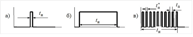
Figure 1.3 – The Form of control pulses of the thyristors
3.2 Classification of PPCS
According to the principle of operation of PPCS are divided into: electronic (semiconductor), built on serial integrated circuits of analog (discrete) and digital type with a low degree of integration; depending on how the control pulses are generated for each thyristor Converter – one electronic unit or individual units-control systems are divided into single-and multi-channel; according to the method of changing the phase of the control pulse, the PPCS are divided into horizontal, vertical and digitally controlled; according to the method of synchronization with the voltage of the network, the PPCS are synchronous (the opening Angle of the thyristors is counted from the voltage of a certain phase of the network) and asynchronous (counted from the moment of receipt of the previous control pulse); electromagnetic, using electromagnetic devices, forming pulses at the time of transition of ferromagnetic materials in the saturated state. Such systems include systems with peak transformers, peak chokes, pulse saturated transformers based on cores with a pronounced knee of the magnetization curve (PPG), single-half-period magnetic amplifiers.
Such systems were produced in the 80s of the twentieth century and are still used as part of the converters of technological equipment of industrial facilities.
3.3 Vertical control principle
Typical PPCS on the principle of management are divided into systems with vertical
and horizontal
control. With the vertical control principle (figure 1.4), the control voltage is compared with the reference alternating voltage (sinusoidal, sawtooth, etc.).
At the time when these stresses become equal and their difference changes polarity, a pulse is formed. The pulse phase can be adjusted by changing the value of the DC control voltage.
The principle of vertical
control applied in most PPCS. The diagrams show that the reference voltage can be either sawtooth or sine (cosine) (figure 1.2).
It is easier to obtain a stable reference sawtooth voltage, because it can be obtained with the help of an integrator and an additional transistor that discharges the capacitance when powered from a stable DC voltage source.
It is difficult to obtain a stable cosine voltage synchronized by the network due to fluctuations in the network voltage and distortion of its shape.
In the batch
control, the pause interval TP between adjacent pulses is not more than 0.5 x off, where the off – time of the thyristor at the maximum anode current. As a rule, tвыкл = 10 x tвкл , so I think that t = tп = (3...5) x tвкл.
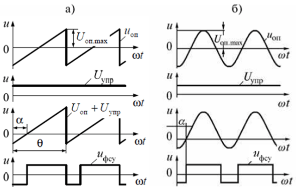
Figure 1.3 – Diagram of voltages and sawtooth) and cosine of b)
In systems with vertical
control, the sweep signal (or input signal) is shifted relative to each other in the vertical plane, as shown in figure 1.4.
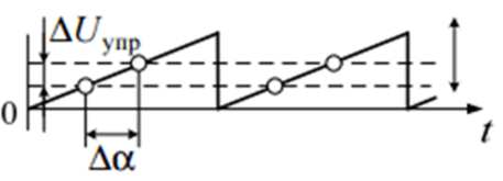
Figure 1.4-Time diagrams of signals in the vertical
control principle of the PPCS
4. Summary
In this paper, a model of the pulse-phase control system of a non-reversible three-phase rectifier assembled in a bridge circuit in Matlab was developed and created. After successful simulation, the PPCS model was loaded into the microcontroller of the STM32F4 Board. To check the performance of the PPCS, the thyristor control signals were removed from the legs of the Board. Impulses corresponded to the requirements presented to them.
Source list
- MATLAB Documentation - MathWorks: [Электронный ресурс]. Режим доступа: https://www.mathworks.com/(Дата обращения: 05.05.2017).
- User manual. STM32F4DISCOVERY [Электронный ресурс]. Режим доступа: http://www.st.com/ (Дата обращения: 05.05.2017).
- Системы управления ведомых преобразователей [Электронный ресурс]. Режим доступа: http://elprivod.nmu.org.ua/ (Дата обращения: 05.05.2017).
- Учебник для вузов
Силовая электроника
Ю.К. Розанов, М.В. Рябицкий, А.А. Кваснюк. - STM32 ST-LINK utility для программатора/отладчика ST-LINK/V2. [Электронный ресурс]. Режим доступа: http://firsthand.ru/ (Дата обращения: 10.05.2017).
- Схемное устройство для распознавания сетевых переходов через ноль [Электронный ресурс]. Режим доступа: http://www.freepatent.ru/(Дата обращения: 20.05.2017).
- Методы и устройства управления тиристорами. [Электронный ресурс]. Режим доступа: http://altay-krylov.ru/ (Дата обращения: 20.05.2017).