
Abstract
Content
- Introduction
- 1. Theme urgency
- 2. Goals and tasks of the research, expected results
- 3. Pulse-phase control system requirements
- 4. Overview of popular microcontroller's families
- 5. Control algorithm implementation
- 6. Model of the system: thyristor voltage regulator – asynchronous motor
- 7. Research of the effect of error
- Conclusion
- References
Introduction
Digital control systems have become widespread in the past few years. In these systems, information is not presented in such signal parameters as voltage or current values, but in numbers, usually represented in binary code. For the formation, transmission and conversion of binary signals in digital control systems, separate elements of digital technology are used, i.e. registers, counters, logic elements, and also microprocessor sets, specialized or universal digital computers.
Digital systems with computer controll can be controlled by software, adding new features without replacing hardware. Often this can be done without the participation of the manufacturer through a simple software update. This feature allows quickly adapt to changing requirements. In addition, it is possible to use complex algorithms that are impossible or feasible in analog systems, but only with very high costs.
Storing information in digital systems is easier than in analog systems. The noise immunity of digital systems allows to store and retrieve data without damage. In an analog system, aging and wear can degrade recorded information. In digital mode, as long as the total interference does not exceed a certain level, information can be recovered absolutely exactly.
The use of digital systems eliminates the main disadvantages of analog control systems. However, it should be noted that the widespread use of digital control systems is still hampered by their high cost and complexity of development.
It is very important that the mathematical description and analysis of most modern digital control systems are based on the methods of analyzing analog systems.
1. Theme urgency
In the process of development of science and technology, the requirements for production processes increase. Since analog systems do not always meet the set tasks, digital control systems are becoming more important.
Analog systems are susceptible to changes in external influences, are characterized by low accuracy of transmission of analog signals over long distances and are laborious to set up. All this leads to a decrease in the quality of control.
In addition, the management of production processes requires a logical linking of various information and data. Therefore, it became necessary to develop a microprocessor-based system for pulse-phase control.
2. Goals and tasks of the research, expected results
The master's thesis is devoted to the development and research of a software algorithm for a pulse-phase control system of a thyristor voltage regulator.
The purpose of the work is to create a software control algorithm, which will be characterized by efficiency, flexibility, high speed and optimality, and also the determination of the influence of the pulse-phase control system error on the system of thyristor voltage regulator – asynchronous motor.
To achieve this goal in the work it is necessary to solve the following tasks:
- develop own control algorithm;
- develop a mathematical model of the thyristor voltage regulator – asynchronous motor system;
- analyze the influence of the control angle error on the amplitude of the oscillations of the moment and the deviation of the engine speed;
- achieve the required accuracy in the formation of control pulses.
3. Pulse-phase control system requirements
The system of pulse-phase control is the set of devices and elements that provides a given sequence of output pulses.
Requirements for the pulse-phase control system of semiconductor converter are determined by the type of semiconductor switch, mode of operation and type of load.
The main requirements for the pulse-phase control system:
- The control pulse must have sufficient amplitude of voltage and current for reliable unlocking of the semiconductor switch (for thyristors 10-20 V, 20-2000 mA).
- In the pulse-phase control system, the steepness of the leading edge of an impulse should be in the range of 150–200 V/el.degrees and more.
- Ensuring the minimum required duration of unlocking pulses (from 5 to 20 µs).
- A wide range of regulation is determined by the type of converter, its mode of operation and the type of the load.
- Control impulses must be symmetrical.
- Pulse-phase control system should not affect on the operation of an adjustable transducer.
Since it is necessary to implement an algorithm for controlling a power thyristor voltage regulator, a number of requirements are added to determine the effectiveness of a software solution.
The effectiveness of the control algorithm of the microprocessor pulse-phase control system is determined by the next parameters:
- The possibility of implementing the algorithm based on low-cost single-chip microcontroller (MC).
- The accuracy of the making of time delays for each output channel.
- The flexibility of the algorithm, which allows, without significant modifications, to change the order of switching, including the introduction of additional functions.
4. Overview of popular microcontroller's families
For software realization of the control algorithm is necessary to select the MC. Consider the available options.
AVR – Atmel 8-bit MCs. They have a harvard architecture and a RISC core with a more developed system of commands, which has up to 133 instructions. Most instructions are executed in one cycle. The software is free. All MCs compatible with each other from early to late versions. Programming in high level C language is possible.
Arduino is a platform for the rapid development of various electronic systems. Mainly in Arduino devices are used AVR MCs. The programming language of the platform is based on C/C++. Arduino has completely open software and hardware.
STM32 – 32-bit MC with flash-based memory ARM Cortex-M. The MCs data has a harvard architecture and an improved RISC core architecture. Cortex is a MC core that includes various peripherals. The subfamily Cortex-M is designed for MC applications when low cost and low power consumption is required. MCs STM32 compatible bottom-up
. There is a wide selection of debug boards.
There are other fairly common family of MCs, such as:
- MCS 51 – 8-bit single-chip MC with harvard architecture from Intel;
- MSP430 – 16-bit MC with von-neumann architecture by company Texas Instruments;
- PIC – 8, 16 and 32-bit MC with harvard architecture by company Microchip Technology.
But they do not have significant advantages compared to the systems discussed above (AVR and STM32 MC families).
Next, we consider the advantages and disadvantages of each taken decisions.
MCs AVR by Atmel company have the following characteristics:
- RISC-processor core architecture;
- 8-bit microprocessor core;
- harvard architecture (storing instructions and data in different address spaces);
- 32 8-bit general purpose registers;
- non-volatile flash-memory of programs 1 up to 256 Kb;
- the number of flash rewriting cycles is 10,000;
- non-volatile EEPROM data memory from 64 bytes to 4 KB;
- the number of rewriting cycles EEPROM 100 000;
- SRAM RAM from 64 bytes to 8 KB;
- I/O ports – from 3 to 86;
- timer-counters – from 1 to 4 8-bit/16-bit;
- watchdog timer (WatchDog Timer);
- analog comparators;
- interrupt support;
- PWM-modulator (PWM);
- multichannel analog-digital converter;
- interfaces: UART, SPI, TWI, JTAG, USB, CAN, LIN;
- supply voltage range from 1.8 V to 5.5 V;
- various sources of clock pulses: crystal oscillator, external or internal RC oscillator;
- clock frequency from 1 MHz to 20 MHz;
- real time clock RTC (Mega family);
- several power saving modes;
- architecture optimization for high level C language;
- sufficient amount of free development funds;
- compatibility of MCs with each other from early to late versions;
- the ability to simulate the operation of the MC in the environment of the Proteus software package.
Disadvantages AVR MCs:
- insufficient speed;
- low clock frequency;
- small number of timers;
- lack of direct memory access in most models.
Arduino platform features:
- easy mastering and development;
- Arduino and C++ programming languages;
- free programming environment
Arduino IDE
, which runs on the operating systems Windows, Macintosh OSX and Linux; - USB programming (no programmer required);
- a wide range of different expansion cards;
- supply voltage range from 7 V to 12 V;
- AVR MCs are mainly used (the Arduino Due is based on the Atmel SAM3X8E ARM Cortex-M3 microprocessor).
Disadvantages of the Arduino platform:
- high cost of ready-made boards;
- low speed;
- most platforms are built on AVR MCs;
- more suited for rapid development and amateur projects than for industrial solutions;
- mandatory firmware loader in the MC memory size of 2 KB;
- surround executable code;
- insufficient compactness of ready boards.
Characteristics STM32 MCs by company ARM Limited:
- RISC-processor core architecture;
- 32-bit microprocessor core;
- harvard architecture;
- non-volatile flash-memory of programs up to 1 MB;
- SRAM RAM up to 320 KB;
- I/O ports up to 168;
- several timers (16- and 32-bit);
- special PWM timers;
- two watchdog timers;
- RTC real-time clock (32kHz internal RC oscillator and 32.768kHz external quartz resonator);
- external quartz resonator 4…26 MHz;
- integrated vector interrupt controller (NVIC);
- 12-bit analog-to-digital converter;
- digital-to-analog converter;
- multi-channel direct memory access (DMA);
- interfaces: UART, SPI, I2C, I2S, JTAG, USB, CAN, LIN, Ethernet;
- supply voltage range from 1.8 V to 3.6 V;
- clock frequency up to 200 MHz;
- temperature range -40…105 ° C;
- sufficient amount of free development tools;
- several power saving modes;
- MCs compatibility
pin-to-pin
and the software code between them; - model-oriented programming is possible in Matlab / Simulink.
Disadvantages STM32 MCs:
- the complexity of the soldering of this MCs;
- more difficult learning to write programs for MCs.
Each of the solutions considered has its own advantages and disadvantages; therefore, the most accessible and popular option, the ATMega AVR MC, was adopted for development.
5. Control algorithm implementation
The implementation of the pulse-phase control system algorithm is reduced to the control of thyristors with the implementation of specified time delays with high accuracy. Time delays are required to be performed independently for each of the channels, and time is counted from the synchronization input.
The first approach (Figure 1) consists of counting the time using virtual counters that are modified by interrupt when one integral timer is overflowed. This approach allows the implementation of a simple pulse-phase control system algorithm, characterized by flexibility and versatility. However, the accuracy parameters in this case will be determined by the interruption period and in practice for the AVR MCs series will be 50-100 µs, which is not acceptable in some cases.
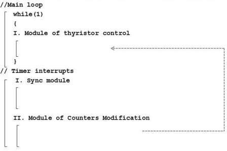
Figure 1 – The first approach to the implementation of the control algorithm
In the second approach (Figure 2), it is convenient to use built-in integrated timers to count the times using the MC tools, taking into account the duration of the counting and the requirements for counting accuracy, these timers should be at least sixteen-bit. At the same time, such timers should be independent for each channel, which is not implemented in the available MCs.
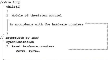
Figure 2 – The second approach to the implementation of the control algorithm
An alternative method is the implementation of time delays using virtual counters that are modified in the main program loop. In this case, the counters are modified by the amount of time that is physically counted by one integrated timer, during which overflow interrupts are not performed. For synchronization the MC input can be used on which the INT interrupt is generated when the signal changes.
The algorithm that implements the principle described above is shown in Figure 3. Practically, the algorithm for modeling and further use is implemented in the C language.
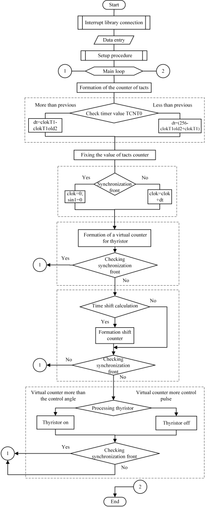
Figure 3 – Block diagram of the software algorithm
6. Model of the system: thyristor voltage regulator – asynchronous motor
Thyristor voltage regulator is a device designed to regulate the voltage supplied to an induction motor. Thyristor voltage regulator consists of three pairs of thyristors, one for each phase voltage. The power elements are included anti-parallel for the flow of a sinusoidal current in two directions.
Thyristor voltage regulators are widely used for speed control and soft start of asynchronous motors of various power. This scheme also provides a reverse, in case of adding two pairs of thyristors.
Changing the control angle is carried out through a system of pulse-phase control.
When developing a software algorithm of pulse-phase control system, the question arises of the necessary accuracy of the supply of control pulses.
To achieve this goal, a model was built (Figure 4) in the Simulink MATLAB, which includes: a three-phase power supply, a pulse-phase control system and thyristor voltage regulator subsystem, an AC motor, a load generating unit, a measurement unit.
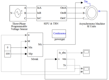
Figure 4 – Model for the study of work pulse-phase control system for thyristor voltage regulator
With the thyristor voltage regulator circuit without a neutral wire (Figure 5), the operation of the phases becomes dependent, therefore, it is necessary to turn on the thyristors in pairs for the corresponding phases. Switching of thyristors is carried out in the following sequence: VS1+VS6, VS6+VS3, VS3+VS2, VS2+VS5, VS5+VS4, VS4+VS1.
Figure 5 – Diagram of thyristor voltage regulator without a neutral wire (animation: 6 frames, 7 repetition cycles, 37.5 kilobytes)
All thyristor control pulses follow each other at intervals of 60°. The control angle, the feed algorithm and the pulse length are described in the m-file. It also sets the value of the control error in seconds and increases the firing angle of the positive thyristor of phase A and the negative thyristor of phase C by the value of this error.
When pulse-phase control system is implementing for a voltage regulator, it was taken into account that when the angle of thyristor control is α>90°, the current within the half-wave of the positive and negative polarity is broken. For it, when the thyristor is turned on in the next phase, a repeated impulse is supplied to the operating power switch.
7.Research of the effect of error
In the course of the research, it was revealed that the moment fluctuations increase with an increase in the pulse supply error. In Figure 6, the dashed line corresponds to the moment in the absence of an error Δt=0µs, and the solid line corresponds to the moment at an error Δt =200µs. The control angle is α=90°. A similar relationship was built for the angle α=120° (Figure 7).
To determine the required accuracy of pulse-phase control system, we construct the dependence of the amplitude of the moment oscillations and the deviation of the angular speed on the magnitude of the error for the control angles α=90° and α=120° (Figures 8,9).
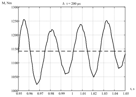
Figure 6 – Motor torque at Δt=0µs and Δt=200µs (α=90°)
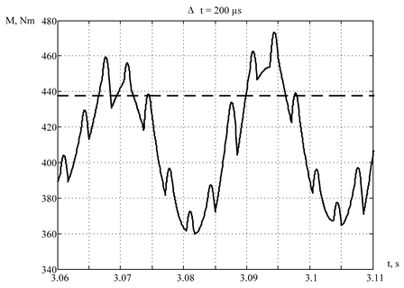
Figure 7 – Motor torque at Δt=0µs and Δt=200µs (α=120°)
The obtained dependences are show an increase in the amplitude of the moment oscillations and a decrease in the angular speed with an increase of thyristor control pulses supply error.
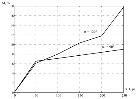
Figure 8 – The dependence of the amplitude of the motor torque oscillations on the control angle error
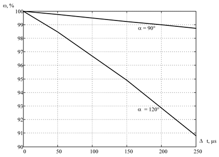
Figure 9 – The dependence of the angular speed motor deviation on the the control angle error
In Figure 8, the permissible error is no more than 38-41µs, since the amplitude of the moment oscillations increases to 5%. For speed, no more than 150µs (Figure 9).
Conclusion
In accordance with the purpose and objectives of the master’s work, theoretical researches of a pulse-phase control system were carried out. The basic requirements for pulse-phase control system are described. Also lists the parameters that determine the efficiency of the microprocessor control algorithm.
The review of known families of MCs was done. Their characteristics are considered in detail, advantages and disadvantages are presented. This made it possible to adopt the AVR MC ATMega series as the most affordable and common option.
The analysis of possible options of the software algorithm implementation was completed. Based on this analysis, developed own alternative approach to the implementation of the control program.
The principle of operation of the thyristor voltage regulator AC motor system was researched, after which the model was compiled in the Simulink application of the Matlab package and its general description was given. On the basis of this model, researches of the influence of supplying control pulses accuracy on the amplitude of the moment oscillations and the deviation of the angular speed have been made. The dependences for the control angles α=90° and α=120° are shown. As a result of the thyristor voltage regulator AC motor system model research, the maximum permissible error of the pulse-phase control system was determined to be no more than 38µs.
At the time of writing this article the master's work is not yet completed. Estimated completion date of master's work: June 2019. The full text of the work and materials on the topic can be obtained from the author or his mentor after the specified date.
References
- Силові напівпровідникові перетворювачі енергії : навч. посібник / О. О. Шавьолкін ; Харків. нац. ун-т. міськ. госп-ва ім. О. М. Бекетова.–Харків : ХНУМГ ім. О. М. Бекетова, 2015.–403 с.
- Полунин, А. И. Оптимизация систем управления плавного пуска ленточными конвейерами / А. И. Полунин, А. В. Лавшонок // Автоматизация технологических объектов и процессов. Поиск молодых ; сборник научных трудов XVI Международной научно-технической конференции аспирантов и студентов, 25-26 мая 2016 г., г. Донецк : в рамках 2-го Международного научного форума "Инновационные перспективы Донбасса".–Донецк : ДОННТУ, 2016.–С. 190–193.
- Datasheet. ATmega16(L)/ Электронный ресурс. Режим доступа: http://www.atmel.com/...
- Программирование на языке C для AVR и PIC микроконтроллеров./ Сост. Ю.А. Шпак–К.: «МК-Пресс», 2006. 400 с., ил.
- Асинхронный электропривод горных машин с тиристорными коммутаторами. Маренич К. Н.–Донецк: ДонГТУ, 1997–64 с.
- Черных, И. В. Моделирование электротехнических устройств в MATLAB, SimPowerSystems и Simulink / И. В. Черных.–Москва : ДМК Пресс, 2007.–288 с.
- Полунин, А. И., Киселева Я. А. Алгоритм управления системой плавного пуска ленточными конвейерами / А. И. Полунин, Я. А. Киселева, А. В. Лавшонок // Автоматизация технологических объектов и процессов. Поиск молодых: сборник научных трудов ХVII научно-технической конференции аспирантов и студентов в г. Донецке 24-25 мая 2017 г. - Донецк : ДонНТУ, 2017.–409 с.
- Дьяконов В. Simulink 4. Специальный справочник.–СПб: Питер, 2002–528 с.: ил.
- C/C++. Программирование на языке высокого уровня / Т. А. Павловская.–СПб.: Питер, 2003.–461 с: ил.
- Куцый О.Я. Программирование на языке Си. Пособие прилагаемое к курсам в Центр Компьютерного Обучения при МГТУ им. Н.Э.Баумана.–Москва: МГТУ, 2010.–84 с.
- Цифровые технологии. Электронный ресурс. Режим доступа: https://ru.wikipedia.org/...
- Васильев К. К. Теория автоматического управления (следящие системы): Учебное пособие.–2-е изд.– Ульяновск, 2001.–98 с.