
Abstract
Content
- Introduction
- 1. Relevance of the topic
- 2. The purpose and objectives of the study
- 3. Review of existing stabilization systems
- 4. The choice of hardware
- 4.1 L298 Dual H-Bridge driver
- 4.2 Chip-down module MP1584EN
- 4.3 Boost Module on Chip XL6009
- 4.4 Radio module NRF24L01+
- 4.5 Current sensor на 5A ACS712
- 5. Test sample model
- 6. Model control panel
- Findings
- List of sources
Introduction
It's no secret that it is human nature to make mistakes, as well as distractions. All this is possible in the process. driving a car. But if a person made a mistake when writing a text, then it will most likely cost several minutes. to correct a mistake. But if a mistake is made while driving, then the possibilities for its correction may not be. In such a situation, electronic assistants installed in the car, who are tirelessly monitor a multitude of sensors and readings in case of an error or emergency on the road to take control and save the situation.
1. Relevance of the topic
Every year the number of cars on the roads only grows, and with it the probability of an accident also increases. To ensure the safety of road users, many driver assistance systems have been created. But simply to create a system and immediately install it in a fully sized car is not rational. To start, you need tests on smaller models, where you can quickly change everything, change configurations and other various parameters. Just for such purposes and a test platform is needed.
2. The purpose and objectives of the study
The aim of the master's work is to create a model of a radio-controlled car as well as a system for its stabilization..
The main objectives of the study:
- Microcontroller selection;
- Select the hardware of the robot;
- Compiling a model stabilization program;
- Analysis of the results.
3. Review of existing stabilization systems
All the safety features of a modern car can be divided into passive (seat belts and airbags, head restraints, etc.) and active (ABS, ESP and others). The main task of active safety systems is to help the driver avoid a possible accident, that is, to prevent the operation of passive safety.
The anti-lock brake system (ABS) was the first active safety system in a car. ABS prevents the wheels from locking at the time of sudden braking and maintains the car’s handling. That is, the system allows you to drive around an obstacle during emergency braking, which will be impossible when the wheels are locked.
With several sensors mounted on the wheels, ABS senses the moment of blocking and takes control of the brakes. The work of ABS can be felt by the vibration of the brake pedal, the main thing to remember is that you can not let go of the pedal. It is necessary, on the contrary, push it harder so that braking remains as efficient as possible.
For more efficient ABS, an electronic brake force distribution system EBD (Electronic Brake Distribution) has been added to it. EBD ensures a uniform distribution of braking force between all four wheels. The system allows each of the wheels to obtain optimal grip. This allows the car to remain more stable during heavy braking.
The effectiveness of emergency braking is very dependent on the force pressing the brake pedal. To help the driver in an emergency, to brake sharply to the ABS one more assistant added – the emergency brake assist system BA (Brake Assist).
BA comes into operation if the driver presses the brake pedal abruptly, but not strong enough.
Many accidents occur because the driver does not have time to press the brake and loses control of the car. To insure the driver from the wrong actions manufacturers began to create systems who independently determine the difficult situation and instantly try to stabilize the car. First of all, we are talking about the ASR anti-skid system and ESP stability control.
The ASR (Anti–Slip Regulation) Anti–Slip System, also known as the TRC (Traction control), is designed to prevent the wheels from spinning.
With the help of ABS sensors, the system senses wheel skidding and reduces engine rpm, and if necessary, brakes the necessary wheels. That is, no matter how hard the driver puts pressure on the gas, he will not be able to achieve a spectacular slip.
But sometimes the system may not allow the car to move. For example, when starting from a very slippery area (ice, snow) the wheels instantly break down into a slip and the ASR is forced to slow them down, while not allowing the car to start moving. To avoid such a situation in the car must be a button off the system.
The ESP (Electronic Stability Program) is considered the most advanced active vehicle safety system.
Combining the capabilities of all previous systems in its work, ESP can not only fix, but anticipate the occurrence of a dangerous situation. For this, the system also uses a number of its sensors. The main ones are the wheel speed sensor, steering wheel position, angular speed and lateral acceleration.
The system comes into action when there is a danger of skidding (demolition) and loss of control over the car. By constantly monitoring all of its sensors, in 20 milliseconds ESP determines what wheels need to be braked and how much it is necessary to reduce the engine rpm to stabilize the movement of the car.
To make it easier for the driver to maintain control over the machine, the most advanced stabilization systems also help turn the steering wheel in the right direction. By interfering with the operation of the power steering, the “advanced” ESP allows you to rotate the steering wheel in the right direction to it much easier than in the wrong direction.
The stability control system has appeared on the car more than ten years ago and during this time it has been updated more than once. improved and supplemented. Each manufacturer in its own way tried to improve it, gave it its name, swapping letters in the abbreviation. But so far no one has come up with an active security system capable of surpassing ESP[1].
4. The choice of hardware
For testing and debugging the program in the course of master's work will be used radio-controlled maelle, also developed during the master's work. The model consists of the following sensors and modules: The down-mount module on the MP1584EN microcircuit, The boost–up module on the XL6009 microcircuit, Radio module NRF24L01 +, Current sensor 5A ACS712, L298 Dual H–Bridge driver.
4.1 L298 Dual H-Bridge драйвер
The L298n is a dual bridge driver for managing bidirectional loads with currents up to 2A and voltages from 4.5 V to 46 V. The microcircuit is designed to control relays, solenoids, DC motors and stepper motors. L298n has TTL compatible inputs. In L298n, there is a power separation for the logic circuit and for the load, which allows you to connect the load with a lower or higher supply voltage than the chip, and also reduces interference.
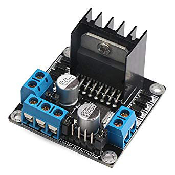
Image 1 – Dual bridge driver L298n
Chip L298n have built–in protection against overheating. The outputs of the chip are turned off when heated to a temperature of about + 70 ° C [2].
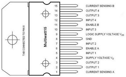
Image 2 – Driver pinout L298n
This driver is very freaked out. The driver bobs down on outdated bipolar transistors, which in the open state have a rather large resistance. As a result, the driver can not withstand a load of more than 2A with an impressive size, and a radiator is always needed to remove heat.
4.2 Chip–down module MP1584EN
This module is a simple MP1584EN [3] pulsed DC down-converter. The module has a low noise level, and this is very important as it provides power to the microcontroller and the radio module, which are very demanding for stable power.
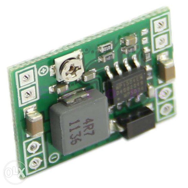
Image 3 – Chip–down module MP1584EN
In our case, the output current of the module does not exceed 300mA, so you can safely use it without a radiator, there will definitely not be overheating.
4.3 Boost Module on Chip XL6009
The module is a XL6009 switching pulse converter implemented on an XL6009 chip [ 1 ]. The microcircuit is quite common for the manufacture of converters and has already been proven by time..
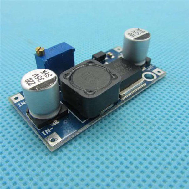
Image 4 – Boost Module on Chip XL6009
In the tests of this transducer in our ratote mode, it turned out that the converter has significant heating of the drosel as well as microcircuits. For heat removal and more safe operation of the converter, it is necessary to provide a radiator for heat removal in the future. or perhaps forced airflow.
4.4 Radio module NRF24L01+
The radio module for communication between microcontrollers. Powered by 2.4 GHz frequency [5] (frequency not requiring permissions, which is also used for WiFi), speed up to 2Mbps, controlled via SPI interface, 3.3V power supply (you can use the output 3.3V of the Arduino board). Significantly cheaper xbee module, well suited for industrial control systems. The range is on open ground up to 100m, within the apartment, through two walls works confidently, after three – there are signal losses.
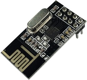
Image 5 – Radio module NRF24L01+
4.5 Current sensor on 5A ACS712
ДThe ACS712 DC driver [6] on the Hall effect allows you to simply integrate it into the circuit and start measuring the current. The sensor is completely ready to work in the microcontroller and does not require additional components. All you need is the presence of an analog input on the microcontroller.
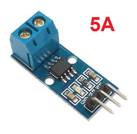
Image 6 – Current sensor on 5A ACS712
Since in our model there are 3 electric motors that create a magnetic field around them, and the current sensor is based on the Hall effect, it is necessary to place the sensors as far as possible from the source of such strong interference.
5. Test sample model
The basis of the robot being developed is the debug Arduino Nano [7] (ATmega328P) [8]. On the platform you can see 3 DC motors, two of which drive the model and one to control the steering mechanism. A debug board and a radio module are installed in the frontal part. Also a driver for controlling the engine turning steering wheels. In the back is the driver L298, which controls two traction motors, as well as current sensors for measuring the current flowing in each motor. Even in the back of the model, two step–up modules are installed which are necessary to increase the voltage applied to the traction drives. The modules are installed in parallel to each other to increase the maximum input current, as well as to reduce the heating of each of their modules. The center has an accumulator battery consisting of three Li–ion [9] batteries of frame size 18650 connected successively to increase the voltage, as well as charge–protection boards.
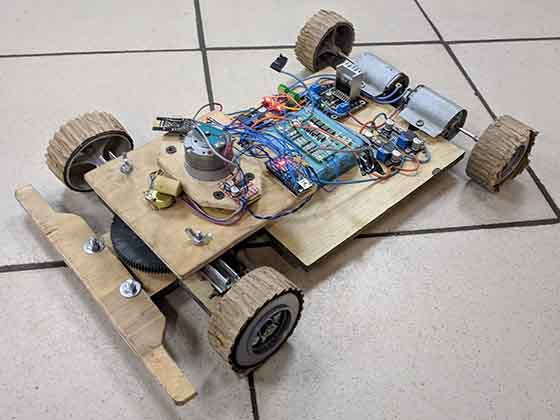
Image 7 – Test sample model
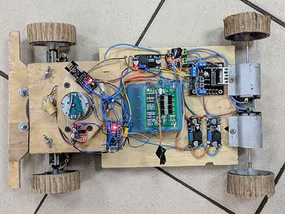
Image 8 – Top view of the model
Image 9 – Demonstration of the steering gear
(animation: 9 frames, infinite loop of repetition, 73 kilobytes)
6. Model control panel
For precise and tactile control of the model, a trigger type remote control was developed and executed. The console allows you to easily and conveniently dispense craving and direction of movement. Thanks to its design, model management is intuitive and does not take long to get used to.
The console works on the exact same bundle of Cantroller – the radio module as the model. It's all the same Arduino Nano and NRF24L01 +. Also on the remote additionally installed is not a big Oled display. The display allows you to display a variety of data on the remote, such as the charge data of the battery model and the remote, motor current measurement data, signal quality and any other data that is needed. At the moment, the data of the charge of the battery of the model and the console, as well as the unprocessed value of the current of the motors are displayed.
The model controls are the steering wheel and pressure trigger. These organs directly affect the potentiometer 10K, which in turn changes the voltage on the analog input of the microcontroller. To return to the zero point, spring mechanisms are provided for both organs. In the future, it makes sense to replace the potentiometers with some kind of contactless position sensor, for example, a hall sensor or an optical sensor.
For long–term operation of the console from one charge, two li–ion batteries of the 18650 form factor connected in parallel were installed to increase the total capacity. To protect and properly charge the batteries, a protection board against overcharging and re-discharging the batteries is installed. The console also has a low–power step–up module. It is necessary to maintain a constant voltage on the microcontroller and not to let the microcontroller supply voltage drop below the permissible limit.
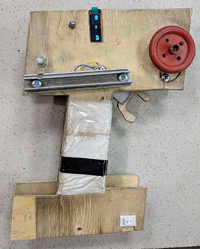
Image 10 – Model control panel
In the future, you can design an ergonomic case for the console and make it with 3D printing.
findings
Based on the work done, it is planned:
- Installing encoders on each wheel.
- Install the MPU9250 sensor for precise orientation in space.
- Finalization of the stabilization program.
- Refinement of the mechanical part of the model and console.
At the time of writing this essay the master's work is not yet completed. Estimated completion date of master's work: June 2018. The full text of the work and materials on the topic can be obtained from the author or his manager after the specified date.
Список источников
- Invisible driver assistants // rikauto.com.ua [Electronic resource]. - Access mode: https://rikauto.com.ua/..., свободный.
- Dual full–bridge drive L298N // tech.dmu.ac.uk [Electronic resource]. - Access mode: http://www.tech.dmu.ac.uk/..., свободный.
- MP1584 – Monolithic Power Systems // monolithicpower.com/ [Electronic resource]. - Access mode:https://www.monolithicpower.com/..., свободный.
- XL6009 Inverting DC / DC Converter // haoyuelectronics.com [Electronic resource]. - Access mode: http://www.haoyuelectronics.com/..., свободный.
- NRF24L01, 2.4 GHz Radio Module // chipdip.ru [Electronic resource]. - Access mode: https://www.chipdip.ru/product/nrf24l01, свободный.
- ACS712 Hall Effect–Based Linear Current Sensor // sparkfun.com [Electronic resource]. – Access mode: https://www.sparkfun.com/..., свободный.
- Arduino nano debug board // amperka.ru [Electronic resource]. – Access mode: http://wiki.amperka.ru/..., свободный.
- High–performance Microchip picoPower 8-bit AVR // microchip.com [Electronic resource]. – Access mode: https://www.microchip.com/..., свободный.
- LI-ION battery type 18650 // aliexpress.com [Electronic resource].– Access mode: https://ru.aliexpress.com/..., свободный.