
Abstract
Content
Introduction
In this paper, given the experience of developing elements of electromechanical hands. In the course of the study, an analysis of several types of mechanical performance of bioelectric prostheses was carried out: using thread thrust, working on a worm gear of translational motion and similar to it piston type, and also of mixed type. For the project, a bioelectric model of a hand with drives for all fingers was chosen. This model is more functional, reliable and capable of making various grip, such as grip on the pinch, when ordinary dentures have only the external, similar to the present, type of arm. The design of the finger was taken from the poster of the St. Petersburg Polytechnic University [9]. Consider its mechanical design. The principle of traction electric drive for each finger was taken to improve the technical characteristics of the device and versatility. Figure 1 shows a model of one part of the brush, the elements of which will consist of the device. It is implemented using 3D printing ABC plastic (see. Fig. 2).
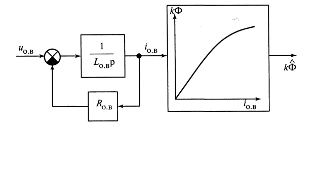
Figure 1 – 3D model of a part of a bioelectric prosthesis
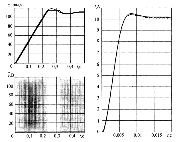
Figure 2 – Designed and created part of the prosthetic arm
Ensuring flexion and extension of the finger is implemented using a gear motor with a built-in encoder. The motor parameters are as follows: rated voltage – 6V, rated speed – 90 rpm, rated torque – 0.7 kg/cm, rated current – 170 mA. According to preliminary calculations, these parameters should have provided sufficient compression force, a bending speed of about two seconds, and an acceptable accuracy of control of the device. The first attempt was unsuccessful: it was not possible to realize a screw gear with the specified characteristics (the thread pitch should have been 11 mm). Next was selected with the usual thread of the bolt M5, whose thread pitch is 0.8mm. In this case, the speed of flexion of the finger was 24 seconds. Therefore, the gearmotor was replaced by the same size, but with a lower gear ratio, which allowed the finger to flex at a speed of 2 s, but it was necessary to sacrifice the compression force. Drawings with the main standard sizes are presented in fig. 3 and 4.

Figure 3 – Finger drawing (side view)
Figure 4 – Finger drawing (top view)
This design is designed to be able to hold large weights not by means of an electric drive, but due to its design. The worm gear allows you to lock the object and prevent it from falling out, and the selected design allows you to turn off the drive motor and lock the object in one position. This saves energy and increases the duration of operation of the device in the autonomous long-term operation. You can increase this figure by replacing the plastic made on a certain metal alloy to enhance the design and reduce backlash between the details of the design.
References
- Усольцев А.А. Общая электротехника: Учебное пособие. – СПб: СПбГУ ИТМО, 2009. – 301 с.
- Теория электродвигателей постоянного тока – электронный ресурс. Режим доступа:
electrikam.com
- Электродвигатель постоянного тока серии ПБСТ – электронный ресурс. Режим доступа:
elektro-dvigateli.ru
- Теория тиристорных преобразователей – электронный ресурс. Режим доступа:
nntu.ru
- Тиристорный преобразователь напряжения БТУ 3601 – электронный ресурс. Режим доступа:
electricalschool.info
- Отладочная плата STM32F4 – электронный ресурс. Режим доступа:
st.com
- Анучин А.С. Системы управления электроприводов: учебник для вузов. – М.: Издательский дом МЭИ, 2015. – 373 с.
- Системы подчиненного регулирования – электронный ресурс. Режим доступа:
ets.ifmo.ru