
Abstract
- Content
- 1. Relevance of the topic
- 2. Description of the object of study
- 3. Review of research and development
- 3.1 Overview of international sources
- 3.2 Review found patents
- 4. Description of the developed mechanism
- Findings
- List of sources
Introduction
Lime is a demanded construction material that is used in various fields. It is irreplaceable, even despite the fact that today there are other modern analogues.
The basis for the finished limestone are kilns. They are widely used in the world due to the simplicity of design and operation. In the world there are many different designs, with different actuators, which are divided into three parts - the boot device, gas or other burners and unloading device. The unloading device is responsible for a number of certain functions, namely, to regulate the speed of burning of the material in the shaft furnace and the direct unloading of lime.
1. Relevance of the topic
However, not all design solutions of this type of device provide the necessary working conditions. One of the main drawbacks are uneven unloading and implementation complexity. The first drawback occurs most frequently, because of which many systems remained on paper and did not go into production use.
The purpose of the study is to compare the already known systems of limestone unloading from a shaft furnace with the developed unloading mechanism. The main task is to compare the systems, find common features and design an installation that will be as efficient as possible and contain at least the shortcomings of the previous ones.
2. Description of the object of study
The main attribute for the production of lime is a kiln for firing this material. In order to produce lime, various types of industrial fuels are used as the burner material: natural, solid, gaseous, artificially solid and liquid. If we talk about the fuel itself, we can distinguish between black coal, natural gas, coke, fuel oil, and other types of combustible fuel suitable for this purpose, and for this furnace design.
The limestone itself is heated in a furnace in the temperature range from 200 to 800 degrees Celsius. Dolomites are heated in the range of 200-600 degrees Celsius. This is accompanied by cracking of the material, and an increase in their volume by about 3-4%, respectively, decreases the compressive strength, the percentage drop is from 40% to 70%. In other words, a process of thermal dissociation occurs, after which a reversible decomposition of the substance takes place. But to complete the process, it is necessary to raise the temperature to at least 1200 degrees.
As is known, for pure limestone, the elasticity during dissociation is equal to the pressure in the atmosphere - 101 kPa at a heating temperature of up to 898 degrees. For other carbonate rocks, this indicator can vary in a very tangible range from 800 to 950 degrees Celsius. During the actual burning of limestone in a kiln, the dissociation temperature is set to between 810-850 degrees; accordingly, the burning rate of the material depends on the temperature inside the kiln, and the coefficient of heat transfer between the materials.
The firing process can be described according to the principle of dividing the shaft furnace into separate thermal zones.
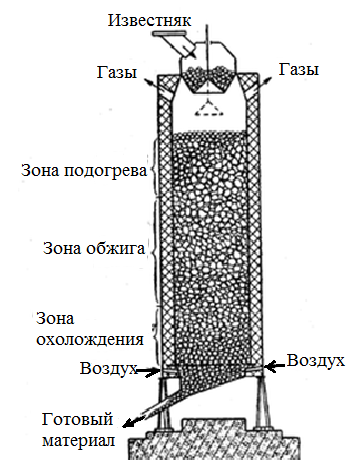
Figure 1 - General view and areas of the processes of burning limestone in the kiln
3. Review of research and development
The main task was to create a model of the developed unloading mechanism, and then describe the principle of its operation. It is based on a hydraulically driven lime unloading mechanism. Then it is necessary to analyze and find structural solutions similar to the device.
3.1 Overview of international sources
After a patent search was conducted, the following foreign patents of mechanisms were found for comparison:
- Pat. 3027147 USA, IPC F27B1 / 21 Circular shaft kiln discharge grate / Brakel L.H .; John B. J .; "Cameron and Jones INC" (US). - № 19590811306; filed 05/06/1959; published 03/27/1962
- Pat. 3854635 USA, IPC B65G65 / 58 Sliding car arrangement for a shaft furnace / Tschinkel F .; "Maerz ofenbau" (CH). - № 19730424706; filed 12/14/1973; Published 12/17/1974
- Pat. 1598451 USA, IPC C10J3 / 30 Discharge mechanism / Saathoff G. W .; "Combustion Utilities Corp." (USA)
These mechanisms have a hydraulic system, they were developed in the USA. They will be compared with the developed analogue, which also has a patent basis.
3.2 Review found patents
1. Pat. 3027147 USA, IPC F27B1 / 21 Circular shaft kiln discharge grate / Brakel L.H .; John B. J .; "Cameron and Jones INC" (US). - № 19590811306; filed 05/06/1959; published 3/27/1962.
The invention relates to continuous-action furnaces with a gravity flow, which are economically beneficial for widespread use in the firing of a variety of solid materials in the crushed material, and more specifically, to unloading devices that regulate the flow of unloaded bulk material.
The unloading device (Fig. 4) is made in the form of a grate of a new design, interacting with the unloaded material in furnaces of a round form of various standard sizes. The device provides uniform distribution of the paged material around the perimeter of the furnace and, consequently, its movement over the shaft section, as well as the ability to control the flow rate.
This in turn allows the material to be processed uniformly in volume with the condition of introducing various reagents at appropriate places inside the furnace.
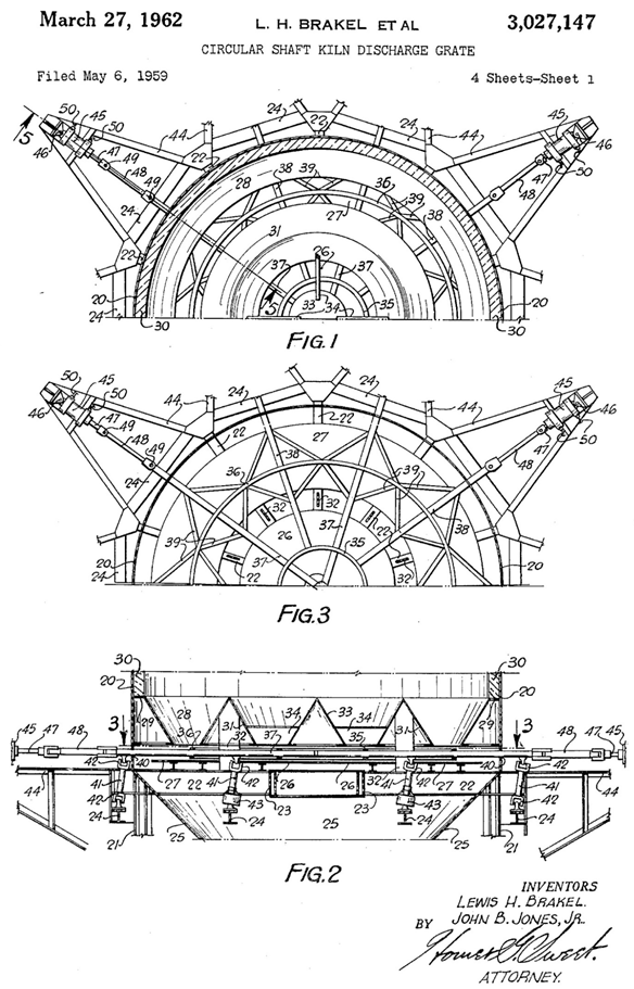
Figure 2 - General view of the mechanism for unloading lime
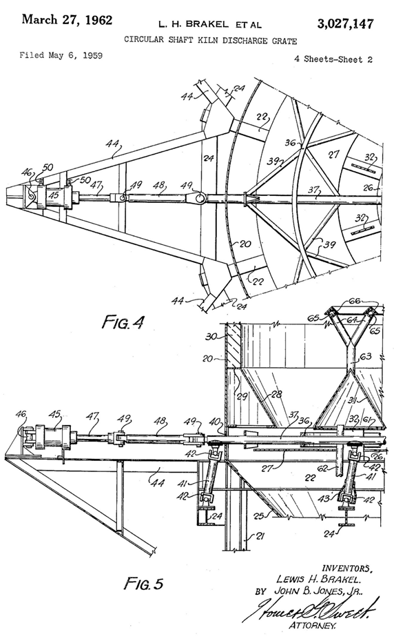
Figure 3 - The main components of the unloading mechanism
2. Pat. 3854635 USA, IPC B65G65 / 58. Sliding car arrangement for a shaft furnace / Tschinkel F .; "Maerz ofenbau" (CH). - № 19730424706; filed 12/14/1973; Published 12/17/1974.
The device for unloading bulk material from the shaft vertical furnace (Fig. 2) is equipped with at least three sliding (sliding) sectors located below the outlet of the mine. Each sector can, independently of the others, move inwards and backwards relative to the center of the mine. In addition, the opposite sectors can be located with the possibility of their driving in a common drive.
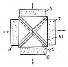
Figure 4 - Orientation of the sectors of the device for unloading bulk material from the kiln: 6, 7, 8, 9 - moving sectors; 10 - furnace shaft; 20 - the arch over the border of neighboring sectors
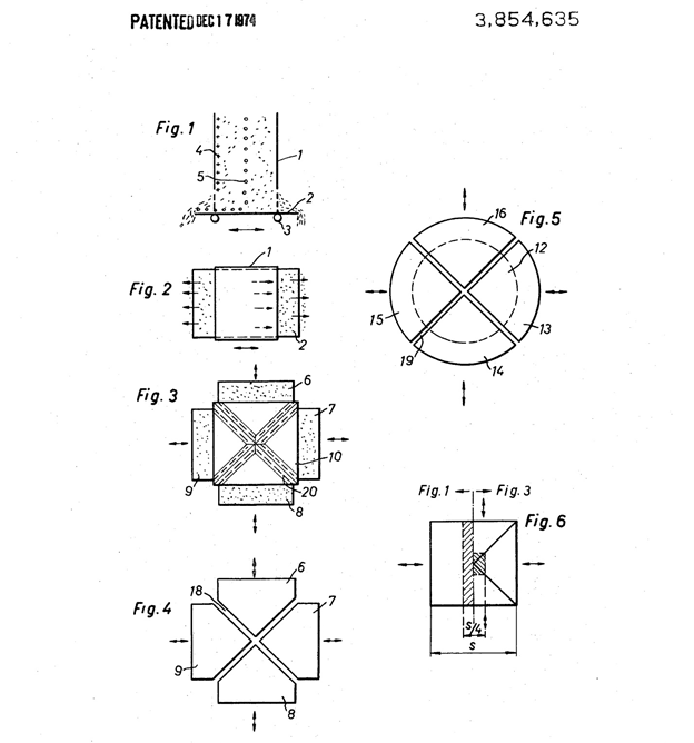
Figure 5 - Orientation of the sectors of the device for unloading and traffic patterns
In the known embodiment of the shaft furnace, whose shaft has a rectangular cross section, the so-called movable table is used as a discharge device. At some distance from the lower end of the shaft, there is a plate mounted on rollers or wheels, and pushed or moved back and forth to unload material from the shaft. With each movement of the movable table, the material is unloaded from one of the two opposite sides of the table, and the column of material in the mine slowly descends to the lower end.
3. Pat. 1598451 USA, IPC C10J3 / 30. Discharge mechanism / Saathoff G. W .; "Combustion Utilities Corp." (USA). - № 19240751886; filed 11/24/1924; published 08/31/1926.
The invention relates to a discharge device and more specifically, to a discharge mechanism for removing coke and ash from gas generators of the mine type.
Some unloading mechanisms for removing coke and ash from shaft type gas generators were designed in such a way that if a column of fuel in the mine was blown up from the periphery - the center - the dissociation of the fuel from the base of the column was arranged more quickly on the periphery than in the center.
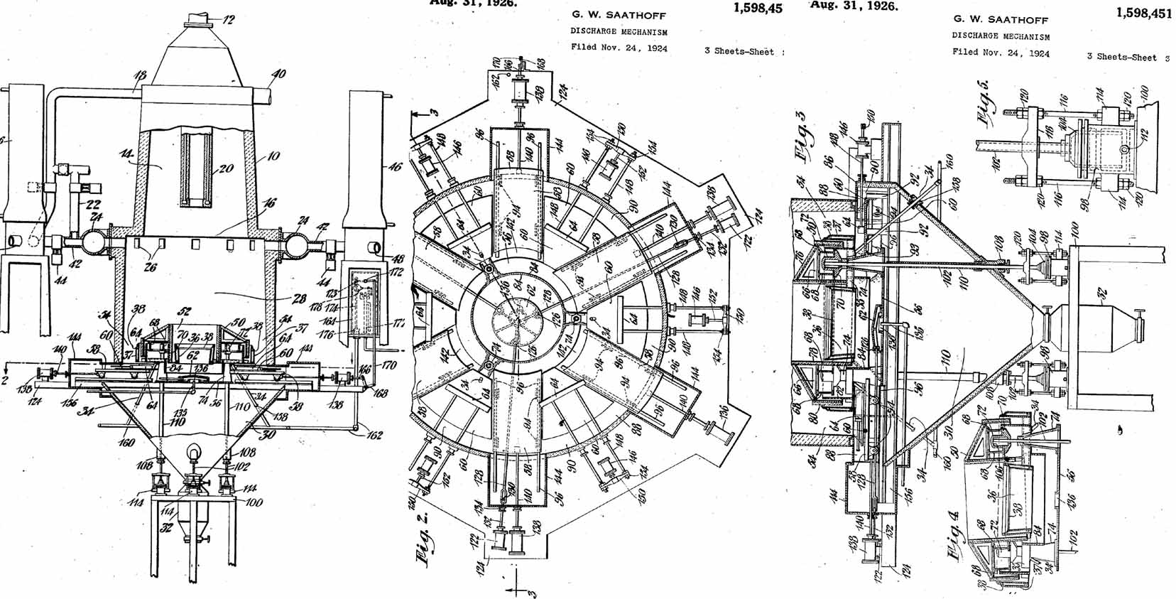
Figure 6 - General view of the mechanism, its devices in different projections
4. Description of the developed mechanism
In the mechanism under consideration there are four interconnected elements - scraper knives. The connection is made with the help of connecting axles, as well as with the slats. The unloading of the finished limestone itself is carried out with the help of knives. This happens due to pouring material through the edges of the unloading table, by pushing it out with knives. At the same time, the main movements are performed exclusively by scraping knives, while the table itself remains stationary. The construction of the mine itself was also changed, and at the end it has a conical end. This is done to ensure that the material with its natural angle of slope does not spill over the edges of the knives themselves.
General view and kinematic diagram of the device are shown below.
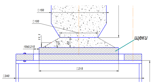
Figure 7 - General view of the unloading mechanism
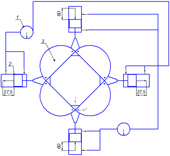
Figure 8 - Kinematic diagram of the mechanism; 1 - pump; 2 - hydraulic cylinder; 3- scraper knife.
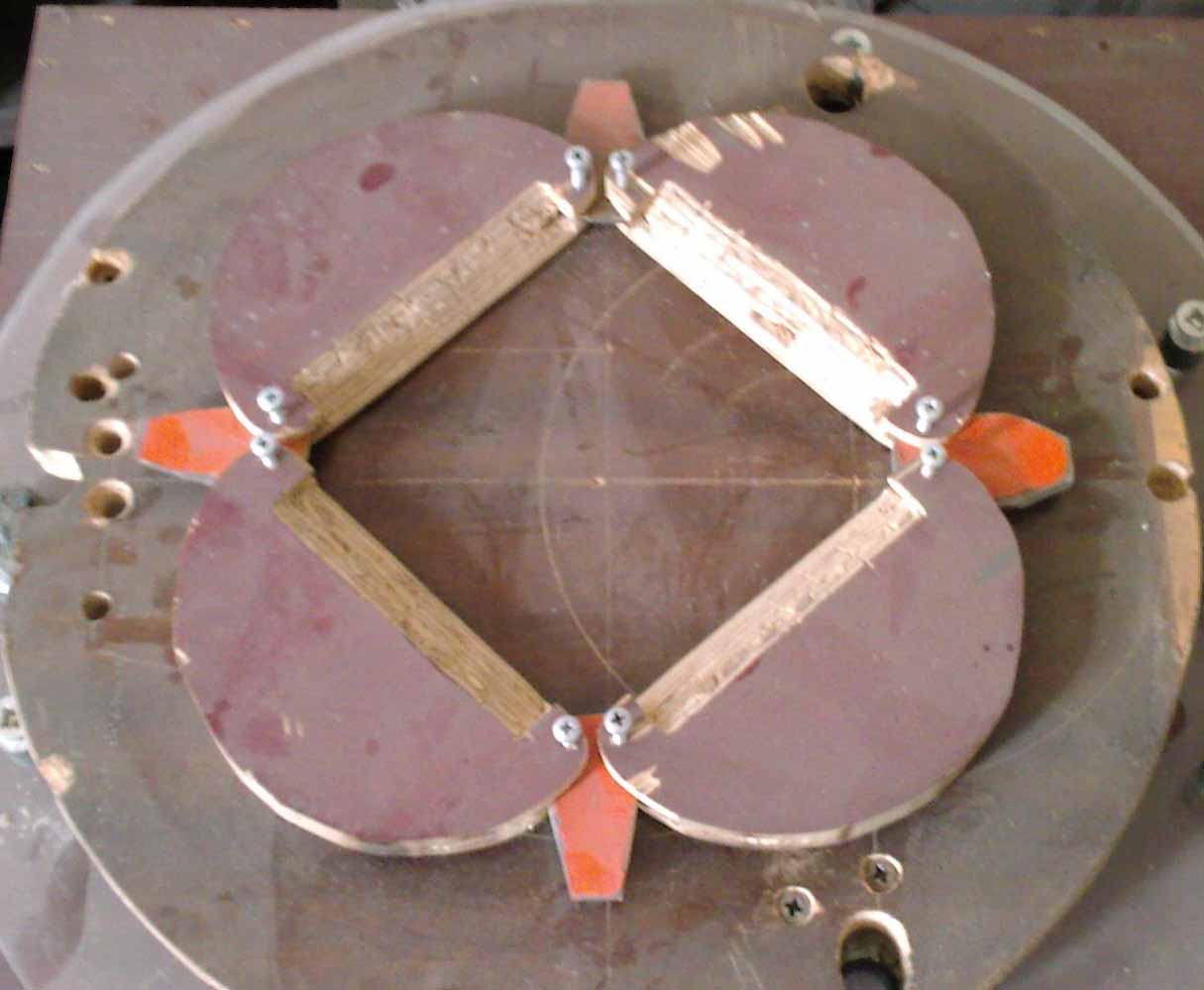
Figure 9 - General view of the unloading mechanism.
The principle of operation is tied to the hydraulic system, which consists of two pumps and four hydraulic cylinders. The cycle of their movement is directly connected to the line. The entire system is powered by two pumps at the same time, and while the two cylinders work to stretch the scraper knives, and move 27.5 millimeters backward, the other two cylinders compress the knives, and move 60 millimeters forward. Exactly the same principle of work, and in the opposite direction only with the change of movements of the executive pair. Accordingly, the stroke distance increases, since subsequent movements of the hydraulic cylinders occur already from the working position of the elements. Such movements burnt limestone poured over the edges of the table.
Findings
As a result, some patents for inventions were found that were as similar in design as possible and were identical in nature to the actuating mechanisms. All of them were listed in the report along with their drawings and descriptions. After this, an analysis was carried out that revealed the shortcomings and similarities of the systems under consideration.
As it turned out, there are many systems that are very similar in construction and character of movement, including actuators. Some of them are very difficult to operate, while others are simple. But for the most part, they all share a common flaw — uneven or fast material unloading. It is also worth noting that the technical implementation of some of them is very difficult and their use may not be appropriate.
Further research is aimed at obtaining experimental data and developing a calculation system with obtaining theoretical dependencies.
At the time of writing this essay, the master's work has not yet been completed.
List of sources
- Advanced patent search - Google; [Electronic resource]. - Access mode: Advanced patent search.
- Patents for inventions of the Russian Federation and patent search in libraries of Russia and other states; [Electronic resource]. - Access mode: Patents for inventions of the Russian Federation.
- Patent search in the database of patents and inventions registered in the Russian Federation and the USSR, free patent research; [Electronic resource]. - Access mode: Patent search in the base of patents and inventions of the USSR.
- Расчеты печей силикатной промышленности. В.Н. Гурина, И.Б. Ревва – 2-е издание, Томский политехнический университет. 2011 г.
- Печи для производства извести, Справочник А.В. Монастырев, А.В. Александров. «Металлургия», Москва – 1979 г. – 10-70 с.
- Приводы машин: Справочник/В. В. Длоугий, Т. И. Муха, А. П.Цупиков, Б. В. Януш; Под общ. редакцией В. В. Длоугого. – 2-е изд., перераб. И доп. – Л.: Машиностроение, Ленингр. отд-ние, 1982. – 383 с.
- Башта Т. М. Гидропривод и гидропневмоавтоматика//М., «Машиностроение», 1972, 230 с.
- Монастырев А.В., Александров А.В. Печи для производства извести.Справочник. – М.: Металлургия, 1979. – 232 с.
- Табунщиков Н.П. Производство извести. – М.: Химия, 1974. – 240 с.
- Монастырев А.В. Производство извести. – М.: Высшая школа, 1978. –225 с.
- Производство извести и сатурационного газа на сахарных заводах / Н.П. Табунщиков, Э.Т. Аксенов, Р.Я. Гуревич, Л.Д. Шевцов. – М.: Легкая и пищевая промышленность, 1981. – 176 с.
- Баренбойм А.М., Галиева Т.М., Гинзбург Д.Б. и др. – М.: Строй-издат, 1964.
- Левченко П.В. Расчеты печей и сушил силикатной промышленности.– М.: Высшая школа, 2002. – 368 с.
- Никифорова Н.М. Теплотехника и теплотехническое оборудова-ние предприятий промышленности строительных материалов и изделий. – М.: Высшая школа, 1981. – 270 с.
- Огнеупоры и огнеупорные изделия. – М.: Издательство стандартов, 1975. – 671 с.
- Воробьев Х.С., Мазуров Д.Я. Теплотехнологические процессы и аппараты силикатных производств. – М.: Высшая школа, 1965. – 773 с.