
Summary of the final work
Content
- Annotation
- Introduction
- Relevance of the topic
- The purpose and objectives of the research, planned results
- Overview of existing skip winches
- Conclusions
- List of sources
Annotation
The article reviewed the structures of skip winches of blast furnaces. Calculated summary indicators of design excellence. The proposed scheme skip winch with reversed rotor.
Introduction
The purpose of blast furnace production is to obtain iron from iron ores by processing them in blast furnaces. The raw materials of blast furnace smelting are fuel, iron and manganese ores and flux. The coke smelting coke is used as a fuel for blast smelting. Its role is to provide the process with heat and regenerative energy. In addition, coke loosens the column of charge materials and facilitates the passage of gas flow in the blast furnace charge. Iron ores contribute to the blast furnace chemically bound with other elements iron. Restored and carburizing in the furnace, the iron goes into cast iron. Manganese is introduced into the blast furnace with manganese ore to produce pig iron of the required composition. Gumboil are additives added to a blast furnace to lower the melting temperature of waste rock ore, to flux coke ash and impart slag physical and chemical properties required by the iron smelting technology. For ores with siliceous (acidic) bare rock, materials containing oxides of calcium and magnesium, such as limestone and dolomitic limestone, are used as a flux. To obtain high technical and economic indicators of blast-smelting, trouble-free operation of all mechanisms is necessary.
Relevance of the topic
The main element of the whole chain is a lifting device that feeds charge materials to the top, the entire subsequent cycle of work depends on its uninterrupted operation. Skip lifts are usually used for furnaces of small and medium size, the main one of which is the skip winch. To date, there are several types of skip winches that have proven their reliability for decades. Scope of skip hoists – blast furnaces up to 2300 m3. The design of the skip winches, the load-lifting element of the skip hoist, has been worked out for decades to provide the necessary performance and high level of operational reliability.
Figure 1 – Blast furnace loading diagram (animation: 13 frames, repetition cycles – 6, size 72 Kb)
The master’s work is devoted to an actual scientific task of studying the parameters of a skip winch when using an inverted rotor in the construction of a winch drive as a method of increasing efficiency.
The purpose and objectives of the study, the planned results
The purpose of the study is to determine the rational parameters in a skip winch with a reversed rotor: overall dimensions, mass, power, rotational speed (speed and mass of the lifted load), clearances, landings, lubrication modes, repair-suitability.
The main objectives of the study:
- Optimize engine dimensions and parameters – diameter, length, mass of the outer rotor and speed.
- Exact stopping by installing disc brakes (the error should not exceed 20 cm).
- Reducing the friction coefficient by installing bearings and lubrication systems.
- Adjustment of the gap between the stator and the rotor (should be 5 mm).
- Open for inspection and increased maintainability.
Object of study: skip winch with reversed rotor.
Subject of research: parameters of skip winch with reversed rotor.
As part of the master's work, it is planned to obtain relevant scientific results in the following areas:
- Determination of the calculated overall and power parameters of the winch with a reversed rotor.
- Determination of the most appropriate structural arrangement of the skip winch.
- Getting the dependencies of the developed speed on time, with different gaps between the staor and the rotor.
Overview of existing skip winches
The uninterrupted supply of charge materials to the charging device of the blast furnace is currently provided by a conveyor or skip feed. Scope of skip hoists – blast furnaces up to 2300 m3. The design of the skip winches, the load-lifting element of the skip hoist, has been worked out for decades to provide the necessary performance and high level of operational reliability.
At the moment, the automatic control systems for the skip winch are being upgraded through the use of modern converter units and contactless displacement code sensors, and there is a decrease in the number of emergency situations due to the use of benign operating modes. But the constructions themselves that have been tested for decades remained unchanged:
- Single engines
- Dual Motors
Twin-engined in turn are subdivided:
- With a combined gearbox
- With disconnected gear
Based on the review of skip winches designs, the article sets a goal – to determine the main elements and characteristics of a modern blast furnace hoist winch.
The [1] paper shows the design of a single-engine Otis
skip winch (Figure 2). The winch includes the following elements: electric motor 1, working brake 2, chevron gears 3 and 4, drum 5, emergency brake 6, switches: emergency 7, working 8, centrifugal 9. The presence of a complex control system indicates the need to ensure the winch operation in a permanent, safe, automatic intermittent mode.
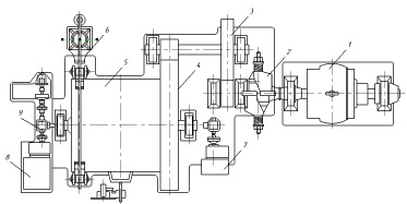
Figure 2 – Scheme skip winch firm Otis
In the future, the task of ensuring the increased reliability of the technological mode of loading was implemented in two motor schemes [2, 3]. The main components of the C-15-180 winch of the UZTM design used on blast-furnaces with a volume of 1000 m3 (Figure 3) are engines 1, gear couplings 2, service brakes 3, gear 4, gear 6, drum 7 and emergency brake 10. The units are mounted on the bed 12. The winch is equipped with control and protection equipment – slack switch ropes 11, centrifugal 9, track 8 and 5. DC motors, controlled by the scheme GD, provide skip stopping with an accuracy of 25 mm.
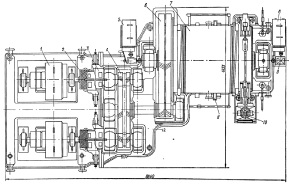
Figure 3 – Skip winch C-15-180
Skip winches C-22.5-210 (Figure 4) and C-29-210 are designed for furnaces with a volume of 1300 ... 2300 m3, have two gears 1, two intermediate shafts 2, transmitting rotation of the drum 3. Thanks to a more reliable gear scheme, the emergency brake is excluded.
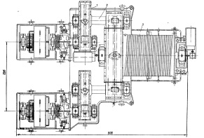
Figure 4 – Skip winch C-22.5-210
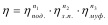
The LS-39-1 skip winch (Figure 5) is designed to work on large-volume blast furnaces – up to 3200 m3.
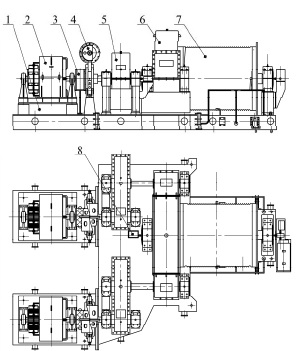
Figure 5 – Skip winch model LS-39-1:
1 – bed frame; 2 – electric motor; 3 – gear coupling;
4 – brake; 5 &??ndash; high-speed gearbox; 6 – low-speed gearbox;
7 – drum; 8 – command device
To analyze the perfection of the design, summarizing indicators were chosen – Efficiency and dynamic coefficient calculated by the generally accepted methods described in [4, 5]. The calculation of the efficiency of the mechanism was carried out according to the formula:
where η under =0.99 – Efficiency of a pair of bearings; η rz =0.98 – Gear efficiency; η muff =0.97 – Coupling efficiency; η 1 , η 2 , η 3 – the number of similar elements: bearings, gears, couplings.
The calculation of the specific energy coefficient was carried out according to the formula given in [5]:

where E – drive energy; N – drive power.
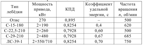
The results of the calculations are shown in the table.
Table – The results of calculations of efficiency and specific coefficient power skip winches
Findings
The blast furnace lift is the main body responsible for the entire further smelting cycle. Any failures lead to downtime and loss of profits. Although there are many different skip winches that have proven themselves well over the years of service, they were all developed decades ago.
Nowadays, when trends dictate their conditions, the loss of mechanical efficiency of almost 20% is very undesirable, and cumbersome designs are not easy to maintain.
This development will help to avoid such costs and at the same time will improve productivity at times.
List of sources
- Щиренко Н.С. Механическое оборудование доменных цехов/Н.С. Щиренко, Учебное пособие. – М.: Металлургиздат, 1962. – 524 с.
- Левин М.З. Механическое оборудование доменных цехов./М.З. Левин, В.Я. Седуш, Киев-Донецк. "Вища школа".1978. – 176с.
- Машины и агрегаты металлургических заводов в 3-х томах. Т.1. Машины и агрегаты доменных цехов/ Целиков А.И. и др. М.–Металлургия, 1987.- 440с.
- Гребеник В. М. Расчёт металлургических машин и механизмов/В. М. Гребеник, Ф.К. Иванченко, В. И. Ширяев, Киев. Вища школа, 1988. - 488с.
- Артюх В.С. Энергия привода – источник динамичности и аварийности металлургического оборудования/В. С. Артюх // Защита металлургических машин от поломок: Міжвуз. темат. зб. наукових праць/ПДТУ. – Маріуполь, 1997. – Вип. 2. – С. 50-57.
- Семикин И.Д.,Аверин С.И.,Радченко И.И.Топливо и топливное хозяйство металлургических заводов. – М.:Металлургия,1965.– 528с.
- Равич М.Б.Эффективность использования топлива. – ВИНИТИ.,М.:Наука,1977. – 344с.
- Филиппов С.И.Теория металлургических процессов. – М.:Металлургия,1967. – 280с.
- Сазанов Б.В.,Ситас В.И.Теплоэнергетические системы промышленных предприятий:Учеб.пособие для вузов. – М.:Энергоатомиздат,1990. – 304с.
- Равич М.Б.Упрощенная методика теплотехнических расчетов.–М.:Наука,1964. – 369 с.
- Сушкин И.Н.Металлургическое топливо. – ,М.:Металлургия,1965.