
Abstract
Содержание
1. Objects of modeling
V-REP simulation models contain several objects or elements that are grouped into a tree hierarchy. The simulation scenes supported by V-REP are described below:
• Articulations: elements that link two or more objects of a scene together, providing one to three degrees of freedom (prismatic, rotational, screw, or spherical). They can operate in various modes (for example, in force / rotational mode, inverse kinematic mode, etc.)
• Shapes: triangular polygonal meshes used to model and visualize solids.
• Proximity Sensors: They calculate the exact minimum distance to the part of the figure that is within detection. This gives a continuous and more realistic simulation than detection based on a large number of directional rays.
• Visual sensors: visual sensors allow you to extract complex images and information from modeling scenes (colors, size of objects, depth of the map, etc.). Built-in filtering and image processing function launches a whole block of filter elements. Visual sensors use hardware acceleration to capture RAW images (support OpenGL).
• Force sensors: they are rigid connections between figures that can record the applied forces and torques, and which can break down when a given threshold is exceeded.
• Graphs: Graphs can record a wide variety of predefined or custom data streams. Data streams can then be displayed directly (a graph over the time of a given data type), or in combination with each other to display X / Y graphs, or 3D curves.
• Cameras: they allow you to visualize scenes that depend on the observation point.
• Lighting: illuminates the scene or individual objects in the scene, and affects cameras or visual sensors.
• Paths: they define complex movement in space (a sequence of freely combined translations, rotations and / or pauses), and are used, for example, to guide the welding torch of a robot along a predetermined path, or allow you to specify the movement of the conveyor belt.
• Material points: these are ancillary reference systems that can be used for various tasks. Mainly used in combination with other objects of the scene.
• Cutters: can be used to simulate the surface of cutting operations on forms (for example, milling, laser cutting, etc.)
2. Computing Modules
Modeling objects are rarely used independently; they rather work on or in conjunction with other objects (for example, the proximity sensor detects shapes). In addition, V-REP offers several calculation modules that can directly work on one or several simulation scenes. The following are the main design modules:
Kinematics module: allows you to perform kinematic calculations (direct and inverse) for any type of mechanism (branched, closed, redundant, containing nested cycles, etc.). The module is based on the calculation of the smallest decaying squares
Dynamic module: allows you to adjust the dynamics of the calculation of solids and interactions (collision, clinging, etc.) using the Bullet Physics Library and the Open Dynamics Engine. Simulations of dynamic systems are still at an early stage and are often based on approximate indicators. To confirm the results, it is important to base not only on one physical engine.
Collision Detection Module: allows you to quickly check for collisions between any shape or set of shapes. This module is completely independent of the response of the algorithms for calculating the dynamics of the module. Used data structures based on a binary tree of rectangular boxes for acceleration. Additional optimization is achieved through caching techniques.
Distance calculation module (Mech-mech module): allows you to quickly minimize the calculation distance between any forms (convex, concave, open, closed, etc.) or a set of forms. The module uses the same data structures as the collision detection module.
Traffic planning module: manual planning of holonomic and nonholonomic problems using an approach based on the Rapidly-exploring Random Tree (RRT) algorithm. Task planning paths kinematic chains are also supported.
As an example of using the V-REP robotic simulator, we will perform an analytical calculation of the trajectory of the ABB IRB 140 robot and compare it with the trajectory obtained using the plotter in the V-REP robotic simulator

Picture 1 – The trajectory of movement of the robot ABB IRB 140 in the V-REP robosimulator
For an analytical description of the path of the output link, it is necessary to determine the coordinate system of the links of the manipulator. Coordinate axes were placed by the Denavit-Hartenberg method.
The method concludes that each coordinate system is formed on the basis of the following three rules [3]:
1) the axis zi-1 is directed along the axis of the i –th articulation;
2) the xi axis is perpendicular to the zi-1 axis and directed away from it;
3) the yi axis complements the xi, zi axes to the right Cartesian coordinate system.
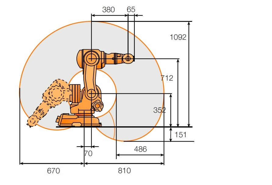
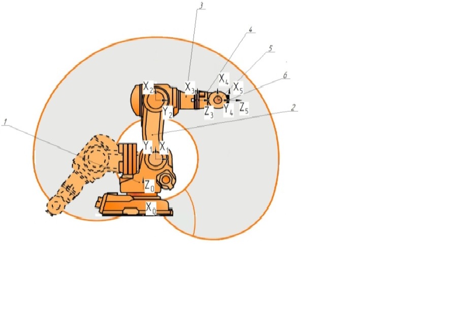
Picture 2 – Sizes and coordinate system of links of the ABB IRB 140 robot
Figure 2b shows the directions of the axes of the coordinate systems of each link work.
A chain of displacements was made from the 0th link (base of the manipulator) to the 5th link, relative to which the particular point is fixed, after which the transformation matrix of Denavit-Hartenberg coordinates for each transition was made (Pic. 3) [4, 5]
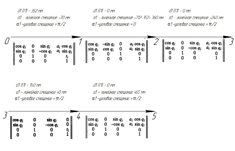
Picture 3 – Link to Link Transition Matrices
In fig. 4 shows the results of solving a direct problem of the position of the manipulator using the Mathcad application software package.
Comparison of the trajectory of the robot, obtained by calculation and using the program.
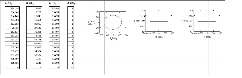
Picture 4 – The trajectory of the robot, obtained by the calculation method
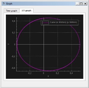
Picture 5 – The trajectory of the robot, obtained using the program
From Picture 4 and 5 we see that the trajectory of a gripping point in the XY coordinate system has a recognizable circle shape, the difference is different numerical values on the coordinate systems, which is explained by the different metric system in the calculation.
Conclusion: V-REP is a versatile and scalable modeling environment. To date, the V-REP has grown to a robust simulator of robots and controllers that is widely used in the scientific and industrial field. It performs a variety of tasks: from system testing, optimization of algorithms, modeling complex assembly chains in automation of production to task planning for robots and controllers.
V-REP is convenient for visual representation of the movements of the robot when solving the kinematic and dynamic problems of the robot arm.
Findings
Enter the research it was proved that this program is adequate, which allows you to use it in further research.
When writing this essay master's work is not completed. The full text of the work and materials on the topic can be obtained from the author or his head.
References
- V-REP – гибкая и масштабируемая платформа для робомоделирования : автор статьи: marc@coppeliarobotics.com - 18 августа 2015, – Режим доступа к журн. : https://habr.com/post/268313/.
- Использование Remote API в робосимуляторе V-REP : автор статьи: Шалыгайло Сергей ar1 - 6 октября 2015, – Режим доступа к журн. : https://habrahabr.ru/post/268313/.
- Представление Денавита–Хартенберга : автор статьи: Studfiles2 - 02.05.2014, - Режим доступа к журн. : https://studfiles.net/preview/985240/page:9/.
- Корендясев А. И. Теоретические основы робототехники: монография : в 2-х кн. / Корендясев А. И., Саламандра Б. Л., Тывес Л. И. ; ред. Каплунов С. М.; Ин-т машиноведения им. Благонравова А. А.. - Москва : Наука, 2006. - . - ISBN 5-02-033952-0. Кн. 1 . - 2006. - 383 с. : ил. - Библиогр. в конце глав. - ISBN 5-02-034439-7.
- Булгаков А. Г. Промышленные роботы: кинематика, динамика, контроль и управление / Булгаков А. Г., Воробьев В. А. - Москва : СОЛОН-Пресс, 2007. - 485 с. : ил., табл.; 22 с. - (Серия "Библиотека инженера").; ISBN 978-5-91359-013-8.
- Учеб. пособие для втузов: В 3 кн. / Под ред. Фролова К. В., Воробьева Е. И.. Кн. 1 : Кинематика и динамика / Воробьев Е. И., Попов С. А., Шевелева Г. И.. – М. : Высш. шк. , 1988. – 304 с.: ил.
- Учеб. пособие для студ. вузов, обучающихся по спец. «Робототехнические системы» / Бурдаков С. Ф., Дьяченко В. А., Тимофеев А. Н. – М. : Высш. шк. , 1986 г. – 264 с.
- Учеб. пособие. – 2-е изд., перераб. и доп. – К.: Выща шк. , 1991 г. –311 с.
- Промышленные роботы в машиностроении: Альбом схем и чертежей: Учеб пособие для технических вузов / Соломенцев Ю. М., Жуков К. П., Павлов Ю. А. и др; Под общ ред Соломенцева Ю. М. – М. : Машиностроение, 1986 – 140 с.
- Костюк В. И., Гавриш А. П., Ямпольский Л. С, Карлов А. Г. Промышленные роботы. Конструирование, управление, эксплуатация. К. : Виша шк. Головное изд-во, 1985 г. – 359 с.