Abstract
Content
- 1. Technological scheme of the mine workings degassing system
- 2. Composition and principle of operation of the mine workings degassing system
- 3. Functional diagram of the monitoring and control system
- List of sources
1. Technological scheme of the mine degassing system
The relative number of mines where gas-dynamic phenomena take place increases every year. Therefore, at present, the development and implementation of degassing systems that allow to extract methane from coal seams and use it are relevant.
One of the very effective ways to ensure safe atmospheric conditions in high-gas-rich excavation sites and to remove the restrictions of the gas factor on the load of the working faces is the degassing of methane emission sources.
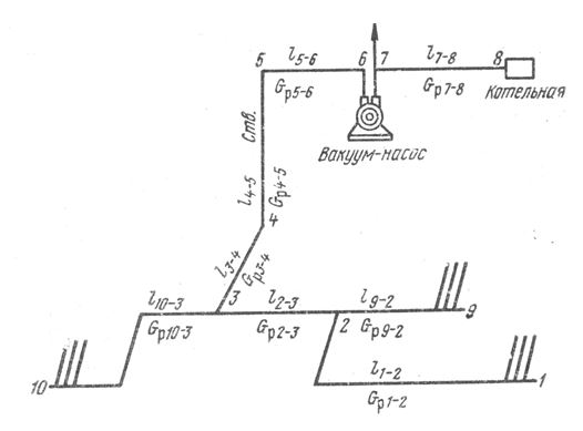
The typical structure of the mine-drainage system is shown in Figure 1. The degassing system consists of gas-drainage wells distributed in space, a gas-suction pipeline (Fig. 2) laid along mine workings, the wellbore and on the surface of the mine, a vacuum pumping station on the surface. Wells are connected to the gas extraction pipe. Each well is equipped with a barrier, water separator, nozzles for vacuum measuring, well flow and methane concentration by portable devices and for installing stationary sensors.


Each well has a limited service life, due to the maximum allowable minimum flow rate of the well and the concentration of methane in the methane-air mixture.
At the end of the service life of the well, the equipment is dismantled and transferred to a new well. At the wells, plugs are installed, and the wellhead is filled with cement mortar.
The suction gas pipeline, laid on the surface of the mine shaft, is connected to a vacuum pump. The gas is supplied to the boiler room via the discharge pipeline. The vacuum pumping station is equipped with stationary devices for monitoring, measuring parameters and protecting the degassing system.
2. The composition and principle of operation of the degassing system of mine workings
The main task of the degassing system of mine workings is to maintain the required concentration of methane, as well as other aerological parameters in the mine, thereby ensuring the safe conduct of work processes inside the mine.
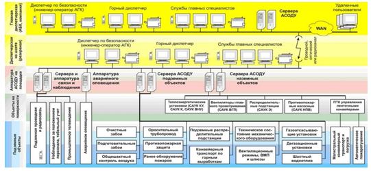
Devices for monitoring and measuring parameters are located on the territory of the mine itself. They belong to the system of aerogas control (AGC). The AGC system includes sensors for monitoring the composition and parameters of the mine atmosphere, equipment for automatic control of air flow, equipment for automatic control of operation and control of local ventilation fans (LVF), audible warning devices and (or) light signaling in underground workings about an emergency situation at a controlled facility, explosion-proof power sources.
All of the above systems are part of the mine’s process control and management system, which looks like this (Fig. 3):

3. Functional diagram of the monitoring and control system
Technical support of the degassing process control and management system is a set of used technical means.
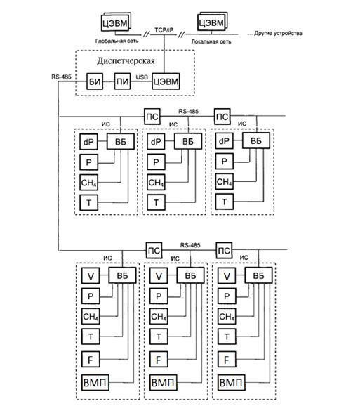
The functional diagram of the system is presented in figure 4.

In general, the operation of the system can be represented as follows: the computing unit included in the measuring station polls methane, absolute and differential pressure and temperature sensors, reads the states of discrete inputs. Based on the data obtained, it calculates the methane production rate and the methane-air consumption rate. MB checks the data to go beyond the bounds of acceptable values and sets the necessary statuses, using all the information received, makes control of the LVF unit.
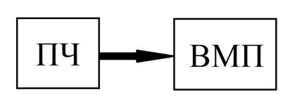
The LVF control unit controls the local ventilation fan drive. The overall structure of the block is shown in figure 5.

By changing the air flow Qin at the input of the LVF, by adjusting the frequency f supplied to the motor voltage as per the task f * for the inverter, the flow Qout is maintained at a given level Q * out. The value of Qout is determined indirectly by the speed of the output flow Vout, the regulation is carried out by the deviation using PID control.
List of sources
- Звягильский Е.Л., Бокий Б.В. Пути совершенствования технологических схем дегазации // Уголь. – 2007. – №12.
- Карпов Е. Ф., Рязанов А. В. Автоматизация и контроль дегазационных систем. – М.: Недра, 1983, – 190 с.
- Колл.авт. Инструкция по дегазации угольных шахт. – М.: Закрытое акционерное общество «Научно-технический центр по безопасности в промышленности», 2012. – 250 с.
- Абдрахманов М.И. Задачи автоматизации дегазационной установки // Материалы Уральской горнопромышленной декады, г. Екатеринбург, 14-23 апреля 2008 г. – Екатеринбург, 2008.
- РЭ АПТВ.М.КП по ст. 1999 г., г. Прокопьевск 2010.
- ГОСТ 6625-85 Вентиляторы шахтные местного проветривания.
- Забурдяев B.C., Бухны Д.И. Особенности проектирования дегазационных систем на протяженных шахтных полях // Безопасность труда в промышленности. – 2012. – № 7.
- Васенин И.М. Математическое моделирование нестационарных процессов вентиляции сети выработок угольной шахты / И.М. Васенин, Э.Р. Шрагер, А.Ю. Крайнов, Д.Ю. Палеев, О.Ю. Лукашов, В.Н. Костеренко // Компьютерные исследования и моделирование. – 2011. – № 2. – С 155 – 163.
- Забурдяев B.C. Дегазация угольных шахт – эффективный способ обеспечения безопасности горных работ в метанообильных шахтах / B.C. Забурдяев, Ю.Ф. Руденко, В.Н. Костеренко, Е.П. Ютяев, Е.В.Мазаник // Безопасность труда в промышленности. – 2010. – №11.
