
Abstract
Content
- Introduction
- 1. Automation Object Analysis
- 1.1 Description of the automation object
- 1.2 Composition and operation of the system
- 1.3 Setting the overall design task
- 2. Review and analysis of well-known object automation solutions
- 3. Designing an automatic control system
- 3.1 Justification of the accepted direction of solving the problem
- 3.2 Functional (structural) scheme of technical means
- List of sources
Introduction
Fireclay - refractory clay, kaolin, burned to the loss of plasticity, removal of chemically bound water and brought to some extent sintering. Today, chamotte is one of the widely used materials in construction. Basically, it is used in refractory materials and for the architectural design of buildings.
One method of producing fireclay is to burn it in rotary kilns.
Despite the wide prevalence of rotary kilns in production, the development of automation systems for this equipment is not at a high enough level, as a result, the control is carried out by the operator, which leads to a potential reduction in the quality of the final product.
The purpose of this work is to develop an automatic control system for a double-drum furnace for the production of fireclay, which will minimize the intervention of personnel in the production process, thereby improving the quality of the final product and reducing the risk of harm to the health of workers, since such production is characterized by high dustiness of air.
The system being developed is applicable to all double drum furnaces that have a similar construction and are used for firing clays.
1. Automation Object Analysis
1.1 Automation Object Description
The automation object is a double-drum rotary kiln for the production of chamotte, a schematic representation of which is shown in Figure 1.
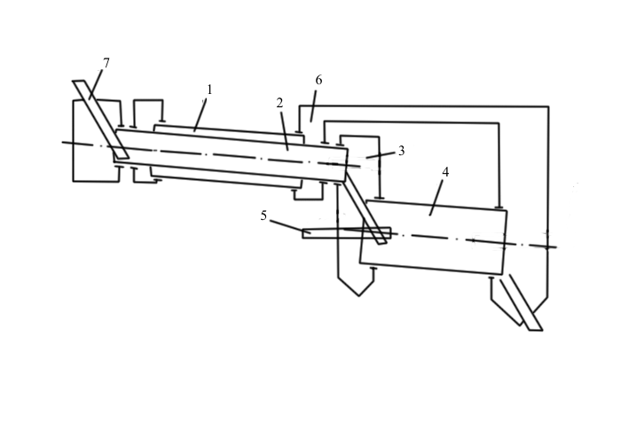
Figure 1 - Schematic representation of a two-drum rotary kiln
A double-drum furnace contains a preliminary heat treatment drum 1, a coaxially built-in drum 2, a pouring chamber 3, a heaving drum 4, a burner 5, a lined recirculation flue 6 and a loading chute 7 installed in it.
The loading chute 7 is located in the built-in drum 2, which is longer than the length of the preliminary heat treatment drum 1. The overflow chamber 3 connects the discharge end of the built-in drum 2 to the loading end of the expansion drum 4, and the lined recirculation flue 6 connects the discharge end of the expansion drum 4 s drum preliminary heat treatment 1 from the discharge end of the built-in drum 2. The burner 5 is located on the loading side of the swelling drum 4 [ 1 ].
The main material of which the furnace is made is steel grade 20X23H18. The lining is made of chamotte bricks of the ShB brand.
1.2 Composition and operation of the system
The main task of the two-drum rotary kiln is the heat treatment and swelling of the raw materials fed to the kiln in the form of raw granules or briquettes.
The prepared raw material is fed through the loading chute 7 into the built-in drum 2. Passing through the built-in drum 2, the material is heated through the walls of this drum with gases passing towards the movement of material through the drum of preliminary thermal preparation 1. At the same time, the material is heated according to the counterflow principle. Hot gases from the expansion drum 4, at a temperature of about 900 ° C, are fed through the recirculation duct 6 into the preliminary thermal preparation drum 1 and heat the raw materials moving in the built-in drum 2 towards the gas flow. When heated raw granules containing an excess of organic substances, the latter are sublimated. The resulting combustible gases together with the material from the built-in drum 2 fall into the swelling drum 4 through the pouring chamber 3, where, mixing with the air coming from the process fuel, they burn with it. Combustion products are sent to the heat treatment drum 1 for heating the pellets.
The arrangement of the burner on the side of the loading end of the drum 4 makes it possible to provide a thermal shock that contributes to the improvement of the swelling of the raw material.
In drum 4, gases and material follow in the same direction along the entire length of the drum, transferring heat from the gases to the material according to the forward flow principle.
1.3 Setting a general design problem
The purpose of creating an automation system is to control the process of burning fireclay.
The system must stably maintain the parameters required by the process to obtain products with the required properties. In particular, in the production of «highly burned» chamotte, the water absorption of the finished product should be in the range of 2 to 10%, and in the production of «low-burned» - 10-25%.
The process is regulated by changing the speed of rotation of the drum and / or by changing the temperature inside the furnace. Also the raw material moisture has a significant effect on the process.
The above is reflected in Figure 2.
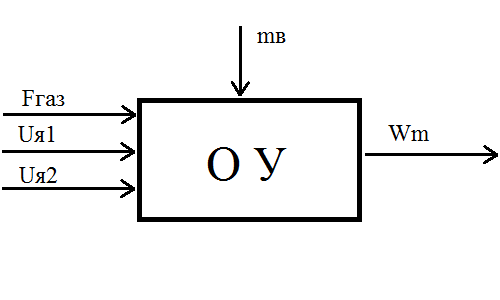
Figure 2 - Drum oven, as a control object
, where Fgas is gas consumption; Uya - the voltage on the armature winding of the engine; mb is the mass of wet raw materials; Wm - water absorption of the final product by weight.
As an output, we will create a list of tasks whose solution is necessary to control the furnace:
- motor control, to provide the necessary speed of rotation of the drums;
- burner control to ensure the required temperature;
- Measure the temperature inside the furnace to form feedback.
2. Review and analysis of well-known object automation solutions
As mentioned earlier, drum furnaces are practically not provided with automatic control systems. In turn, during their production various SKADA systems are laid down, designed to monitor various production parameters, to signal, when errors occur, and allowing the furnace to be remotely controlled.
Since, today, most productions use single drum furnaces, consider, for example, the SKADA system of such a furnace (Figure 3) [ 2 ].
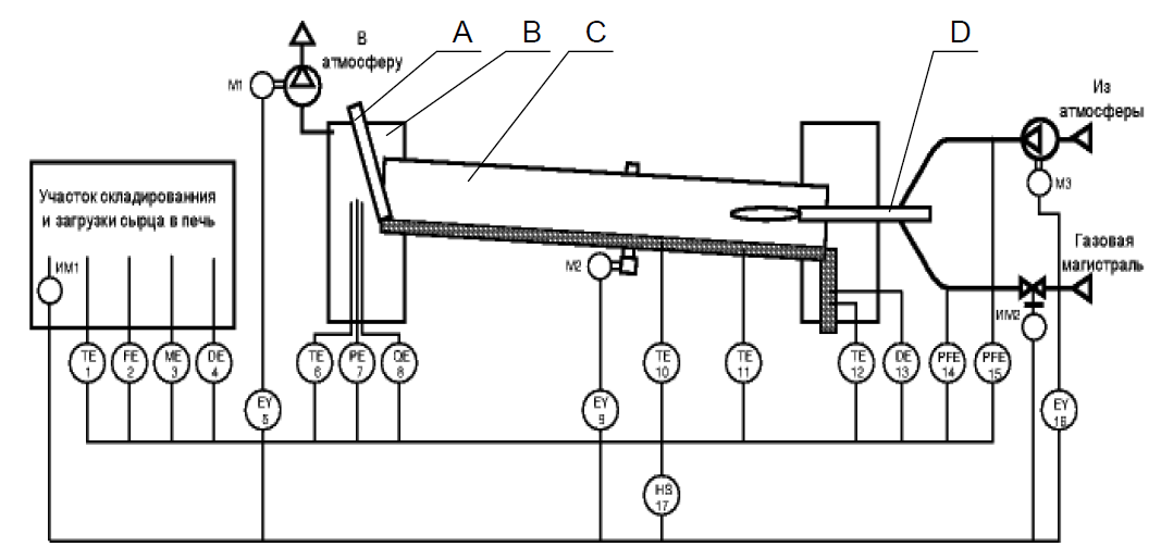
Figure 3 - Functional diagram of the SCADA system of the rotary kiln
In this diagram, the following functional units of the furnace are designated: loading device A, dust-collecting chamber B, rotating furnace C and burner D.
In turn, the SCADA system is conditionally divided by the authors into two parts (one is responsible for monitoring technological parameters, the second is for remote control).
The system allows you to control the following key technological parameters:
- temperature (position 1), consumption (position 2), humidity (position 3) and density (position 4) of raw material when it is loaded into the furnace;
- temperature (pos. 6), vacuum (pos. 7) and chemical composition (pos. 8) of exhaust gases in the dust precipitation chamber;
- the temperature of the calcined material in two sections of the furnace: at the end of the preparation zone (pos.10) and in the middle of the expansion zone (pos.11);
- temperature (position 12) and density (position 13) of the finished product at the exit of the furnace;
- pressure and flow rate of gas and air (pos.14, 15) supplied to the burner.
The operation mode of the furnace is controlled by changing the following technological parameters:
- furnace loading amount - with the help of the actuator of the IM1 feeder;
- exhauster capacity - by controlling the speed of the M1 engine;
- the frequency of rotation of the furnace drum - by controlling the speed of the engine M2;
- the flow rate of air supplied to the burner is controlled by the speed of the M3 fan motor;
- the flow rate of gas supplied to the burner is carried out using an actuator actuator IM2.
Despite the fact that this SCADA system was developed for a single drum furnace, it can also be used for a double drum furnace, making some changes. Also, the authors suggest further improvement of the system by adding algorithms and control systems for existing process equipment, which allows us to use this system in the development of ACS.
It is also worth noting that drum furnaces, despite the differences in design and raw materials, have the same principle of operation and, accordingly, the same (or most similar) control algorithms, which is confirmed by [ 3 ] and [ 4 ].
3. Designing an automatic control system
3.1 Justification of the accepted direction of solving the problem
Considering what was said in the previous paragraph, the SCADA system shown in Figure 2.1 will be used as the basis for the development of the ACS, however, for its normal operation, some changes are necessary.
The main difference between the object in question and the object for which the SCADA system was developed is a different number of drums.
For a single drum kiln, the firing curve, according to A.S. Fadeeva [ 5 ]., Looks like this:
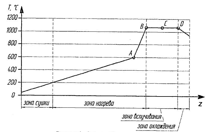
Figure 4 - Curving firing of raw materials in a single-drum furnace
The coordinate axis Z denotes the length of the furnace and its values ??may vary, however, the general view of the graph remains unchanged.
In the same work, it was stated that points A and C are optimal places for installing temperature sensors. At these points, various disturbing influences and variable factors have minimal effect on the sensors, which allows you to track the temperature inside the furnace as accurately as possible.
Given that the drums of a double drum furnace perform different functions (heating for one drum and swelling for another), we can arbitrarily divide the above graph into two parts through point B. Based on this, we can conclude that one temperature sensor is sufficient for each drum which, however, must be at the points shown on the graph.
Also, having two reels means having two engines that require separate control from each other [ 6 ].
3.2 Functional (structural) scheme of technical means
In view of the above, a block diagram of the technical means of the system has been drawn up.
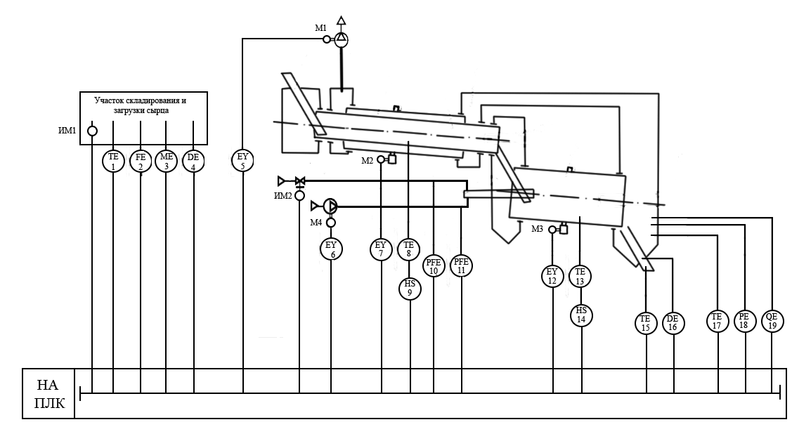
Figure 5 - Structural diagram of technical means
The principle of operation of the system is as follows: wet material, through a loading chute, is fed into the drum of preliminary thermal preparation, which also receives hot air, through a recirculation flue duct. When the drum rotates, the particles of solid material move along its axis. In the opposite direction, hot air passes through the drum, giving off heat to the material particles and evaporating the moisture in them. The dried material is poured into the heel drum, where it warms up even more. In this drum, the air moves in a forward flow with respect to the movement of the material. The dried material is sent for cooling, and the exhaust gases, through the flue, are sent to the drum of preliminary thermal preparation.
As a source of data for the controller, enter the temperature and humidity of the exhaust gases, as they can be used to judge the indicators of the output product. These values ??should be pre-calculated in the laboratory. Also, for a more rapid exit of the machine to the operating mode, it is advisable to specify the speed of rotation of the drums for the supplied amount of raw materials and the gas / air ratio of the burner. Due to the self-regulation of the control loop, intervention in the furnace working process will be necessary only in cases of force majeure or, if necessary, a change in the input or output product (change in the grade of clay supplied or the grade of burnt chamotte). For the stability of the roasting process, it is recommended to ensure a predetermined flow of raw materials into the furnace [ 7 ].
List of sources
- Двухбарабанная вращающаяся печь // Патент СССР № 1516721. 1989. Бюл. № 39 / В.Е. Гиндина, А.А. Ахундов, В.В. Титов, Л.Л. Новикова.
- М.А. Назаров, А.С. Фадеев, В.М. Горин, В.И. Гаршин. Структура SCADA-системы вращающейся печи обжига керамзита. Материалы Международной научно-технической конференции Интерстроймех 2014. Самара, 2014. 104-106 с.
- Serge Naud, Martin Emond. Lime kiln control using simple advanced regulatory control strategy [Электронный ресурс]. - Режим доступа: http://www.topcontrol.com.
- Kurt E. Peray. The Rotary Cement Kiln. Second Edition. / Kurt E. Peray // New York: Chemical Publishing Co., Inc. 1986. – 389 pages. ISBN: 071313609X.
- Фадеев А.С. Автоматизация технологического процесса вспучивания керамзита во вращающейся печи: автореф. дис. … к.т.н. Самара, 2011. 20 с.
- Kurt E. Peray. Cement Manufacturer’s Handbook / Kurt E. Peray // California: California Historical Society, 1979. – 408 pages. ISBN: 0820603686.
- Шевченко А.В., Фадеев А.С. Постановка задачи автоматизации двухбарабанной печи производства керамзита. Традиции и инновации в строительсте и архитектуре. Самара, 2014. 490-493 с.