Abstract
Iordanov R. V., Zavadskaya T. V., Kushnirenko Ye. N. – Main steps of robot designing The stages of designing a mobile robot are determined. The article suggests the implementation of the main stages of design. The block diagram of the robot is given. Modern technologies are offered as development tools. Based on the elaborated mathematical apparatus and the structural diagram, the final model of the robot is presented.
Keywords
robotics, design, structural diagram, mobile robot model, simulation, behavior
Introduction
Nowadays the robotic technology is the most progressing area. Main objectives which are pursued by engineers during creation of robots are facilitation of work and lowering of risk for human life [1]. Thus, implementation of robotic systems allows changing the rate of development of different branches significantly.
This article deals with the problem of robot creation. In particular, the stage of simulation and simulation of robot behavior is considered.
Problem definition
The proper organization of robot designing plan is necessary for reducing quantity of possible errors at each work stage. After determining of input data and the main tasks which robot has to do the project work is as follows:
- To determine robot technical appearance, its systems and subsystems. Structural diagram compilation.
- To choose the basic functional elements.
- To develop mathematical apparatus.
- To choose development tools.
- To create the robot model.
- To simulate the robot behavior. To test it.
- Work prototype creation.
This plan reflects the main steps of development. The feature of such organization is a possibility of return to the previous stage to eliminate the arisen errors.
Realization
Based on the structural diagram shown in figure 1, the robot model was created.
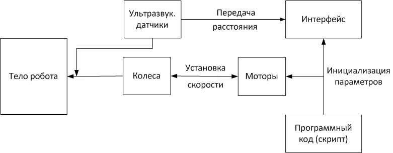
Figure 1 – Structural diagram
The model includes such components as: ultrasonic sensors, motors, wheels, program code. Ultrasonic sensors are sensors whose operation is described by echolocation. The ultrasonic sensor sends a pulse, marking the time of its return back, and thus the robot is oriented in space.An important advantage of ultrasonic sensors is their non-attachment to the time of day. Sensors successfully manifest themselves both at night and daytime, which significantly expands the range of their use. The behavior of the mobile robot is autonomous.
Motors and robot wheels are attached to the body in such a way as to ensure sufficient stability of the model. The wheel axle is shifted a few centimeters from the center of the body of the robot along the X axis and the third passive wheel (slider) is directly opposite. The slider is also equipped with a force sensor and, in case of excessive load on this element, it is disconnected. The need for such a design is explained by the importance of calculating the mass of each of the elements, as well as the entire model as a whole
There are dangers not the precise course of the simulation and the incorrect behavior of the model, when the mass does not correspond to the required values. Too little robot weight leads to its inability to turn, accelerate, while too much weight can prevent the model from moving.
Three-wheeled bases are convenient in that there is no need to take into account a large number of elements. Programming the motion of such systems is much simpler, but at the same time the robot will successfully cope with the tasks set.
To organize the movement of the mobile robot, a mathematical apparatus was developed. It allows to connect the received data from the sensors and on their basis to influence the system of movement of the model.
After initializing the sensors, it is necessary to read the data using the read function. The function work is related to the moment when the main script starts the part responsible for activating the sensors. After execution, the function returns some parameters necessary for the further course of the simulation.
The received parameters are the result, and some distance. The result is the status of the sensors: an obstacle is detected, not detected, an error occurred. Distance is the distance from the sensors to the detected obstacle point.
The distance is checked for the distance restriction condition: if the available distance is less than the limit, the next step is executed. In other words, the robot overcame the predetermined limitation of detecting obstacles by the sensors and successfully determined the obstacle. The next step is to calculate the point for each sensor.
The wheel speeds are then corrected according to the following formulas [1, 2]:

where  – wheel speed in previous moment of time, W – braitenberg’s coefficients, Dist. – calculated distance of the detected point in the previous step.
Block diagram of described algorithm is shown in figure 2:
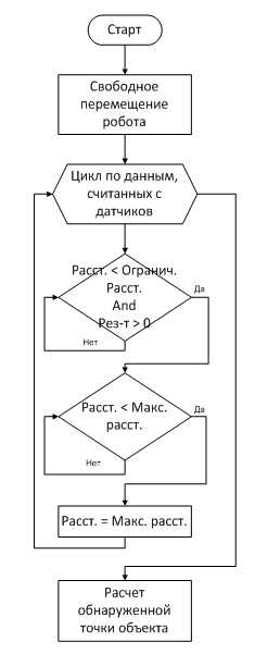
Figure 2 – Block diagram of algorithm
Modeling occupies an essential part of time while robot development [2]. Creation of model allows to organize the logic of robot movements, systems and subsystems work. Also at this stage there is an adjustment of the given tasks.
The model is provided in figure 3:
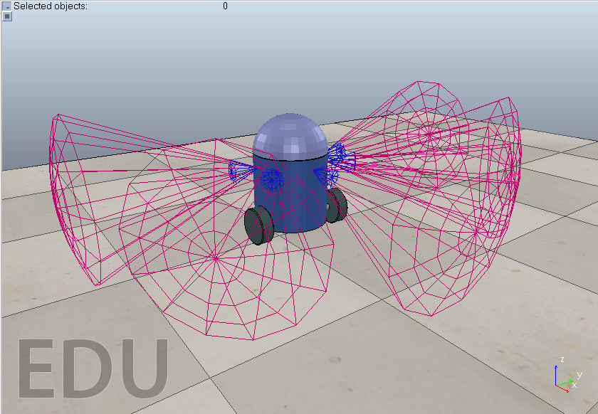
The model was developed using the V-REP robot simulator (Virtual Robot Experimentation Platform) [3], which met all the requirements for the development of the model. In particular, providing a mode of simulating the mobile robot behavior in real time and flexible configuration of the main components.
After creation of model data retrieved are analyzed. In case of absence of errors, preparation for simulation is organized. Simulation is meant as support of different conditions and during tests response of the robot is monitored. The created conditions allow to study behavior of the robot comprehensively. Adjustment of results in case of erratic behavior of robotic system is also mandatory.
The creation of the user interface is an additional component of the simulation of the robot and its subsystem. The interface includes the following elements:
- Function buttons for closing and minimizing the window;
- Speed change slider;
- Motor blocking checkbox.
When starting the simulation, this window will be displayed in the program window of V-REP. It is assumed that the window has functional folding and closing keys for extending the usability of the interface.
The speed change slider is required to test the model balance. This solution allows you to verify the accuracy of the assembly of all elements of the robot and, in case of incorrect behavior, correcting the position of the elements, the masses of the model after the termination of the simulation.
The blocking of motors is used in the event that the robot has failed and it is urgent to take measures to avoid an accident without stopping the simulation. The use of this measure is aimed at approximating the simulation to the real work of the robot.
In general, the presence of the interface significantly increases the capabilities of the projected model, and also allows the user to participate directly in the simulation.
In conclusion it should be said that the process of modeling gives the possibility to create robot model, to check the adequacy of his work, to choose the research conditions and to eliminate the errors.
Proceeding it, six steps of classical robotic system development were executed.
References
1. Robotics [Electronic resourse] .– Access
mode: https://en.wikipedia.org/wiki/Robotics
2. Modeling stage [Electronic resourse] .– Access mode: https://knowledge.allbest.ru...
3. V-REP [Electronic resource] .– Access mode: http://www.coppeliarobotics.com/