
Abstract
Contents
- Introduction
- 1. Theme urgency
- 2. Goal and tasks of the research
- 3. Overview of researches and developments
- 3.1 Overview of international sources
- 3.2 Overview of local sources
- 4. Approach to verifying the correctness of the solution of problems of descriptive geometry
- Conclusion
- References
Introduction
Training in many disciplines related to descriptive geometry has long been closely intertwined using computer technology. Now it is difficult to imagine a solution to the problems of descriptive geometry without using a computer. Best of all, special computer systems cope with teaching students. In such systems, the student can not only read about how the solution to a particular task is built, but also see the model from all sides if it is in space. If the model is made in the form of a complex drawing, then most often there is also the possibility of its rotation. Some of these systems go further than just a demonstration of the solution. They can also check the correctness of the solution of the problem by the student. About the latter and will be discussed.
1. Theme urgency
There are many textbooks, manuals, and other teaching materials describing the solution of basic geometric problems by which students can independently study descriptive geometry. One of the problems of such self–learning is the self–verification of the correctness of problem solving. Hence the need to develop an automatic verification system.
Similar self test systems already exist. After analyzing them, it was decided to develop their own system, taking into account the advantages and disadvantages of the analyzed systems. The system being developed will have to check every step of the student’s solution to a particular task and, if an error is found, inform him about it. The system will be able to verify solutions to problems both in a complex drawing and in space.
The basic tool for geometric modeling will be AutoCAD, and the tool for implementing problem solving algorithms is the AutoLISP language [1].
2. Goal and tasks of the research
The aim of the work is to develop and create our own automated system for checking the correctness of the student's solution of descriptive geometry problems in the field of basic geometric shapes, polyhedra, and developable ruled surfaces.
The tasks in developing such a system are:
- Analysis of similar systems.
- Accounting for the advantages and disadvantages found in them when developing their own system.
- Development of own algorithms for verifying the correctness of the solution.
- Adding the possibility of expanding and modifying the system in the future.
The result of the work should be a convenient and practical training system for automatically checking the correctness of the student’s solution of descriptive geometry problems with the possibility of expanding and modifying the system in the future.
3. Overview of researches and developments
Now more and more gaining the popularity of teaching students through interactive systems. Many university professors are looking for more and more new, more effective methods of teaching descriptive geometry in order to interest students more to study it than just to give a number of laboratory works and manuals for their implementation.
In his work Computer modeling in the education system
Z. K. Abdurakhmanov. considers issues related to the implementation of modeling in
the education system for the training of specialists capable of successful adaptation and self–realization in a developed
information society [2].
In the work of Bogdanova E. E. Methods of teaching descriptive geometry in technical universities: some aspects of practical training of
students
considers the indispensability of the science Descriptive Geometry
as an integral part of general engineering education; changing
the approach to the study of descriptive geometry, new methods and means of its development, as well as methodological techniques using modern
computer technologies and the dependence of the efficiency of mastering the Descriptive Geometry
discipline from both proven teaching methods
and new techniques related to the use of modern information technologies [3].
3.1 Overview of international sources
Foreign teachers are also interested in the implementation of interactive systems in the educational system of universities.
In the article An on–line library of descriptive geometry problems
, Eduardo Toledo Santos and Jose Ignacio Rojas Sola describe an interactive
system on the Internet that implements an electronic library of descriptive geometry problems. All tasks in it can be available in the form of
proposed exercises or solved tasks (demonstrations). The library can register several alternative solutions for the same task, allowing the user
to choose the one that he understands better. The system is implemented as a client–server architecture. The server part works together with the
web server and manages the database of tasks and registered users. The client part is represented by a Java applet that provides graphical
interaction with users. Drawing tools are available for online problem solving. Demonstration of the solution is carried out using step–by–step
animations and explanatory texts. The system has several simple learning opportunities [4].
Also, Eduardo Toledo Santos, together with Andre Luis L. de Oliveira and Leandro Lourenzoni, have an article entitled A real world metaphor
interface for an educational geometry drawing software
which describes the drawbacks of drawing–related program interfaces. Among the
shortcomings were highlighted such as high complexity, involving the waste of time studying the interface instead of the target content,
the lack of similarity with real drawing tools and others. The article offers its own solutions to problems with the interface. Following the
direct manipulation, the specific style of the metaphor of the real world, the elements of the proposed interface have similarities with the
real tools for drawing. For example, a pencil, eraser or ruler. Due to its characteristics, the proposed interface must be very intuitive, do
not require any operating instructions and are able to teach the student the proper ways to use real drawing tools [5].
3.2 Overview of local sources
In Donetsk National Technical University there are also works on similar topics. One of such works is the work of Karabchevsky V. V. and Babkova A. A. "Modeling of processes for solving problems of descriptive geometry" [6]. It presents methods for creating dynamic three–dimensional solutions to problems of descriptive geometry using the 3D Studio Max package (Fig. 3.1).
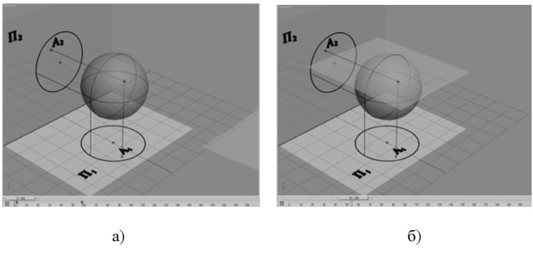
Figure 3.1 – An example of modeling the movement of the section plane [6]
a) starting position b) end position
Using these methods of forming solution models, the process of creating the models themselves is significantly accelerated and their quality improves, which in turn increases students' interest in the subject of descriptive geometry and improves the quality of learning.
Another interesting work of the former master of DonNTU NL Proglyadova N. L. Automatic solution of descriptive geometry problems
[7] describes a system similar to the one being developed. The paper describes the creation of a system for automatically
solving problems of descriptive geometry using AutoLISP language. This system allows you to automatically solve problems only in a complex
drawing (Fig. 3.2).
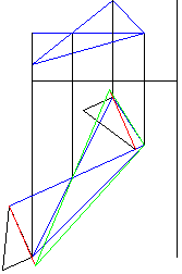
Figure 3.2 – An example of a solved problem on the construction of the full size of the sides of a triangle in a complex drawing [7]
4. Approach to verifying the correctness of the solution of problems of descriptive geometry
Verifying the correctness of the solution is not the only purpose of the system being developed. In fact, the system will consist of two large blocks.
The first block will include the system for automatically solving geometric problems in the AutoCAD environment, which was developed earlier in the bachelor’s work, but with modifications to the code to improve the optimization of the system’s performance. Improvements imply a complete restructuring of the already written code in order to reduce it and increase the speed of the entire system.
The second block will already include the developed system designed to self–test the correctness of the student’s solution to a subset of geometric problems for the section of ruled surfaces in a complex drawing and in space.
To implement such a system, you need to develop your own algorithm for verifying the correctness of the solution. Any construction chosen by the user from the program proposed to him includes the following steps:
- The program prompts the user for input data.
- The user enters input data.
- The program assigns the received input data to the corresponding variables.
- The program prompts the user for the appropriate build on the displayed text description of the build.
- The user performs the corresponding requested build, and the program simultaneously checks the correctness of the build in accordance with the input data.
- If the construction is performed correctly and it was not the last step, then the program displays the explanatory text of the next construction step.
- If the construction is performed incorrectly, the program will display an error message and ask the user to repeat the construction.
- If the construction is correct and this was the last step, the program will request to display on the screen a message on the completion of the construction.
- Display the message about the end of the construction.
The sequence of steps and clarification of their interaction are depicted in Figure 4.1.
Figure 4.1 – Sequence of stages of the system operation at any construction chosen by the user from among those proposed by the program and clarification of their interaction (numbers in the figure indicate the numbers of the stages listed above)
Consider each of the stages in more detail:
- The program prompts the user for input data by displaying the appropriate messages on the command line. After entering the requested parameter and pressing the Enter key, the program checks the entered value for its correctness and compliance with the requested parameter.
- The user takes the input data from the textbook "Methods of Computer Geometry" [8].
- After all the input data have been entered and checked for correctness, the program assigns values to the corresponding variables. The program will use these variables to build its own solution to the problem, which it will use to compare it with the construction of the user.
- Before construction, the program builds the coordinate axes on the screen and adjusts the AutoCAD coordinate system relative to these axes in accordance with the geometric problem to be solved. After that, displays a text explanation of the construction of the first step of the solution and waits for the user to start building.
- In this part of the program, the developed algorithm for checking the correctness of the solution of problems works. An example of its work can be seen in Figure 4.2. It shows the work of the algorithm when checking the correctness of the construction of one of the segments. The algorithm starts its work after the user has finished building a step (in this example, a segment). After point 6 in Figure 4.2, the program decides what to do next. More on this is described below.
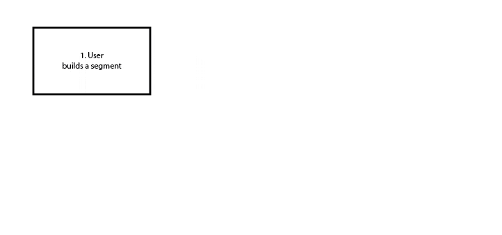
Figure 4.2 – An example of the operation of the algorithm for checking the correctness of the solution when building the initial segment
(animation: 6 frames, 7 cycles of repetition, 31 KB)
Based on the results of the test, the program has three options for action. The first option: the construction is true, but there are still construction steps (the development option described in step 6), the second option: there is some error in the construction, display a message about it on the screen and repeat the construction (development option described in paragraph 7), the third option : the construction is correct, there are no more construction steps, display a message about the completion of the construction (the development option described in steps 8 and 9).
By a similar principle as in the example shown in Figure 4.2, any construction is checked.
Conclusion
From the material studied and analyzed, it is possible to draw an unequivocal conclusion that the use of interactive learning systems of descriptive geometry is a promising direction for the development of student learning in any technical university. To interest a student in the study of a given subject, and not to force him to study a subject, is the main goal of such an approach to learning.
In the course of the research work, we developed our own algorithm for verifying the correctness of the solution of a subset of descriptive geometry problems associated with the section of ruled surfaces in a complex drawing and in space. The developed system using the above–mentioned algorithm contributes to the improvement of education of students of technical universities. Also, this system is easy to expand and modify to improve its work and a greater coverage of the tasks of descriptive geometry.
This master's work is not completed yet. Final completion: May 2019. The full text of the work and materials on the topic can be obtained from the author or his head after this date.
References
- АВТОЛИСП – язык графического программирования в системе AutoCAD [Электронный ресурс]. – Режим доступа: http://kappasoft.narod.ru/info/acad/lisp/a_lisp.htm#2
- Абдурахманов З.К. Компьютерное моделирование в системе образования [Электронный ресурс]. – Режим доступа: https://cyberleninka.ru/article/v/kompyuternoe-modelirovanie-v-sisteme-obrazovaniya
- Богданова Е.Е. Методика преподавания начертательной геометрии в технических вузах: некоторые аспекты практической подготовки студентов [Электронный ресурс]. – Режим доступа: http://publikacia.net/archive/2016/5/4/9
- Eduardo Toledo Santos, Jose Ignacio Rojas Sola An on-line library of descriptive geometry problems [Электронный ресурс]. – Режим доступа: https://www.academia.edu/31732536/An_On-Line_Library_of_Descriptive_Geometry_Problems
- Eduardo Toledo Santos, Andre Luis L. de Oliveira, Leandro Lourenzoni A real world metaphor interface for an educational geometry drawing software [Электронный ресурс]. – Режим доступа: https://www.academia.edu/826273/EDUCATIONAL_GEOMETRY_DRAWING_SOFTWARE
- Карабчевский В.В., Бабкова А.А., Моделирование процессов решения задач начертательной геометрии [Электронный ресурс]. – Режим доступа: http://ea.donntu.ru:8080/handle/123456789/5587
- Проглядова Н.Л. Автоматическое решение задач начертательной геометрии [Электронный ресурс]. – Режим доступа: http://masters.donntu.ru/2004/fvti/proglyadova/diss/
- Карабчевский В.В. Методы компьютерной геометрии. Донецк: ГВУЗ
ДонНТУ
, Технопарк ДонНТУУНИТЕХ
, 2010. – 179 с.